Tri-body variable area fan nozzle and thrust reverser

a technology of variable area fan and thrust reverser, which is applied in the direction of vessel construction, marine propulsion, aircraft navigation control, etc., can solve the problems of not providing additional functionality, complexity and weigh

Active Publication Date: 2009-11-26
RTX CORP
View PDF5 Cites 100 Cited by
  • Summary
  • Abstract
  • Description
  • Claims
  • Application Information

AI Technical Summary

Problems solved by technology

Although effective, this and other conventional thrust reversers serve only for thrust reversal and, when in the stowed position for non-landing conditions, do not provide additional functionality.
Therefore, the problem to be solved is integrating the VAFN functionality with the thrust reverser to reduce complexity and weight.

Method used


Image

  • Tri-body variable area fan nozzle and thrust reverser
  • Tri-body variable area fan nozzle and thrust reverser
  • Tri-body variable area fan nozzle and thrust reverser

Examples


Embodiment Construction

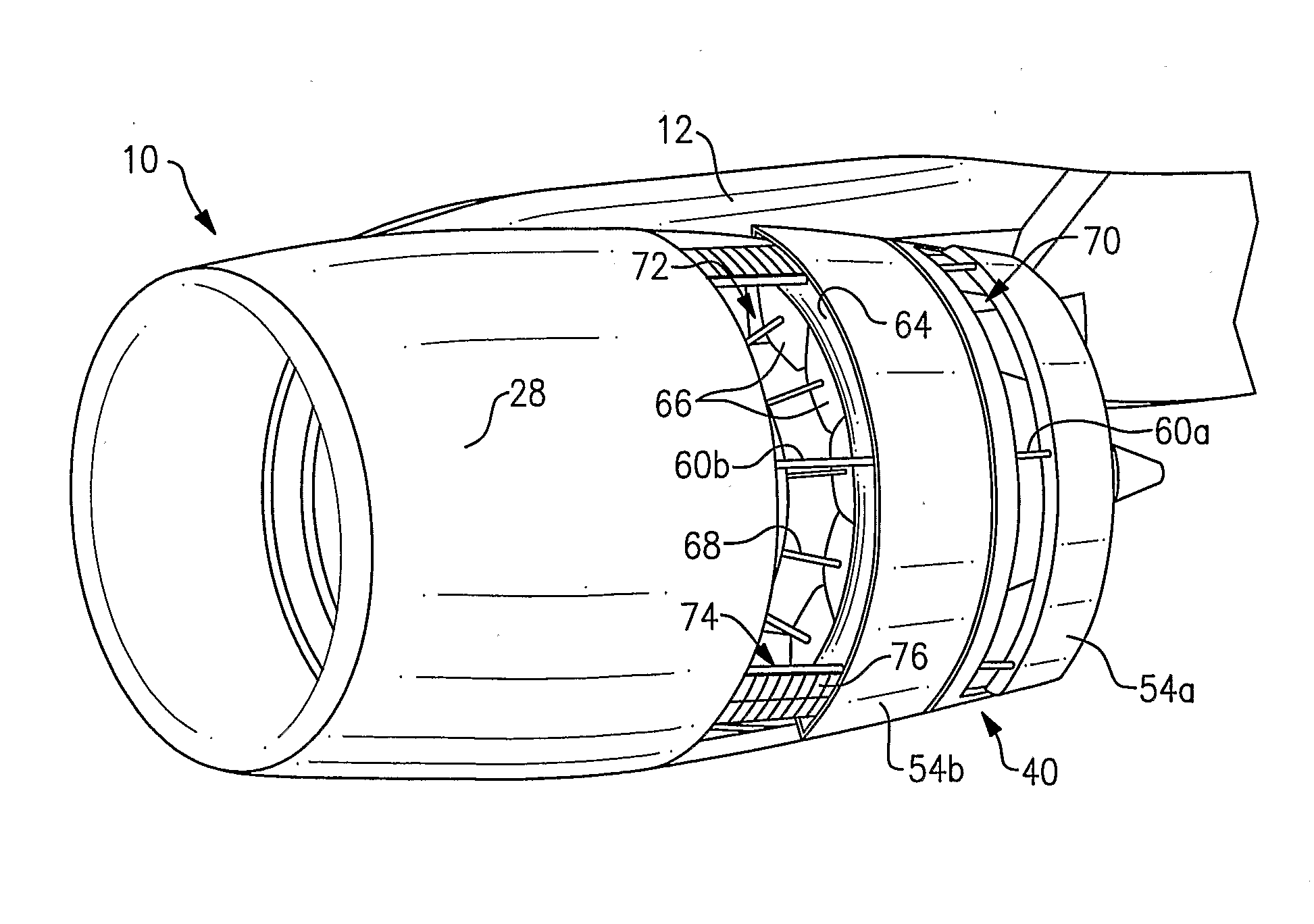
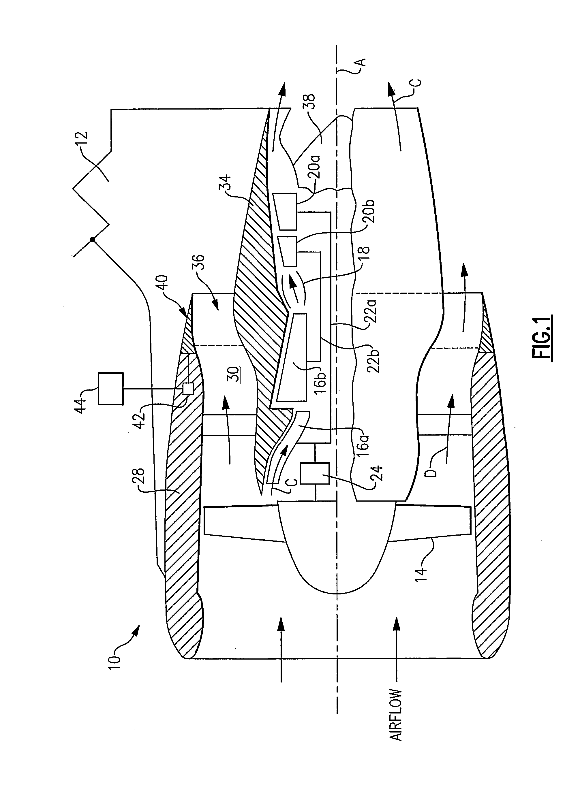
[0012]FIG. 1 illustrates a schematic view of selected portions of an example gas turbine engine 10 suspended from an engine pylon 12 of an aircraft, as is typical of an aircraft designed for subsonic operation. The gas turbine engine 10 is circumferentially disposed about an engine centerline, or axial centerline axis A. The gas turbine engine 10 includes a fan 14, a low pressure compressor 16a, a high pressure compressor 16b, a combustion section 18, a low pressure turbine 20a, and a high pressure turbine 20b. As is well known in the art, air compressed in the compressors 16a, 16b is mixed with fuel that is burned in the combustion section 18 and expanded in the turbines 20a and 20b. The turbines 20a and 20b are coupled for rotation with, respectively, rotors 22a and 22b (e.g., spools) to rotationally drive the compressors 16a, 16b and the fan 14 in response to the expansion. In this example, the rotor 22a also drives the fan 14 through a gear train 24.

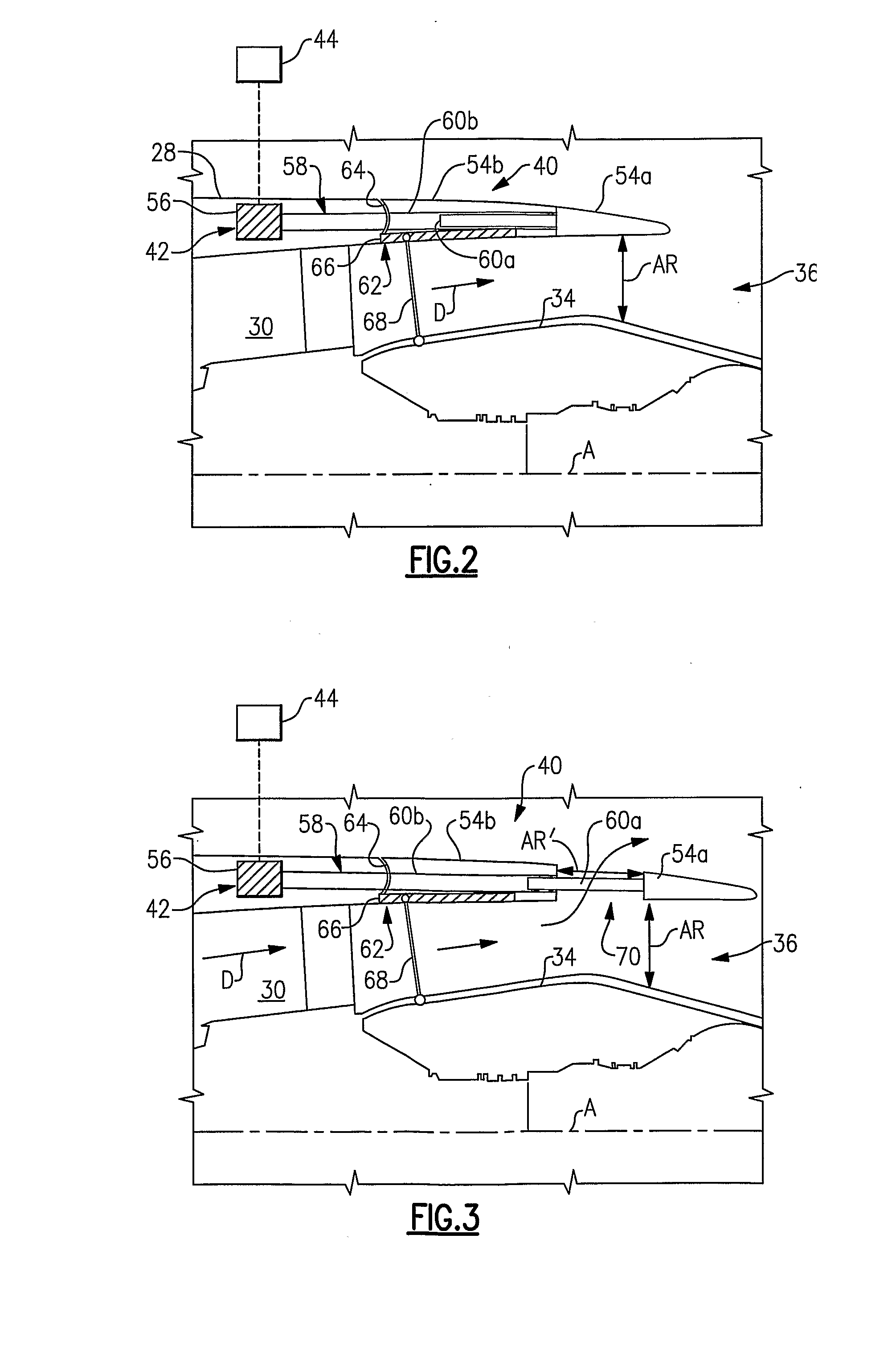
[0013]In the example shown, t...


PUM


Abstract

A gas turbine engine system includes a fan (14), a housing (28) arranged about the fan, a gas turbine engine core having a compressor (16) at least partially within the housing, and a fan bypass passage (30) downstream of the fan for conveying a bypass airflow (D) between the housing and the gas turbine engine core. A nozzle (40) associated with the fan bypass passage includes a first nozzle section (54a) that is operative to move in a generally axial direction to influence the bypass airflow, and a second nozzle section that is operative to also move in a generally axial direction between a stowed position and a thrust reverse position that diverts the bypass airflow in a thrust reversing direction. An actuator (42) selectively moves the first nozzle section and the second nozzle section to influence the bypass airflow and provide thrust reversal.

Description

BACKGROUND OF THE INVENTION[0001]This invention relates to gas turbine engines and, more particularly, to a gas turbine engine having a nozzle that integrates functions of a variable fan nozzle and a thrust reverser.[0002]Gas turbine engines are widely known and used for power generation and vehicle (e.g., aircraft) propulsion. A typical gas turbine engine includes a compression section, a combustion section, and a turbine section that utilize a primary airflow into the engine to generate power or propel the vehicle. The gas turbine engine is typically mounted within a housing, such as a nacelle. A bypass airflow flows through a passage between the housing and the engine and exits from the engine at an outlet.[0003]Presently, conventional thrust reversers are used to generate a reverse thrust force to slow forward movement of a vehicle, such as an aircraft. One type of conventional thrust reverser utilizes a moveable door stowed near the rear of the nacelle. After touch-down of the ...

Claims


Application Information

Patent Timeline
Patent Type & Authority Applications(United States)
IPC IPC(8): F02K1/09F02K1/72
CPCF02K1/09Y02T50/671F02K1/72Y02T50/60
Inventor MARSHALL, RICHARD M.GUKEISEN, ROBERT L.
Owner RTX CORP
Why Eureka
Try Eureka