Operation Device for Quick and Accurate Control of Working Device of Tenoner

a technology of operation device and working device, which is applied in the direction of special profiling/shaping machines, dovetail work, profiling/shaping machines, etc., can solve the problems of difficult to move the molding bar along the undulated edge quickly and accurately, and achieve the effect of quick and accurate manner

Inactive Publication Date: 2009-11-26
YANG JACK
View PDF12 Cites 6 Cited by
  • Summary
  • Abstract
  • Description
  • Claims
  • Application Information

AI Technical Summary

Benefits of technology

[0008]It is an object of the present invention that the elastic member enables the shaft to movably engage with an undulated edge of the guiding member in a quick and accurate manner.

Problems solved by technology

A problem is that it is difficult to move the molding bar along the undulated edge quickly and accurately, and vary the distance between the molding bar and the support bar.

Method used


Image

  • Operation Device for Quick and Accurate Control of Working Device of Tenoner
  • Operation Device for Quick and Accurate Control of Working Device of Tenoner
  • Operation Device for Quick and Accurate Control of Working Device of Tenoner

Examples


Embodiment Construction

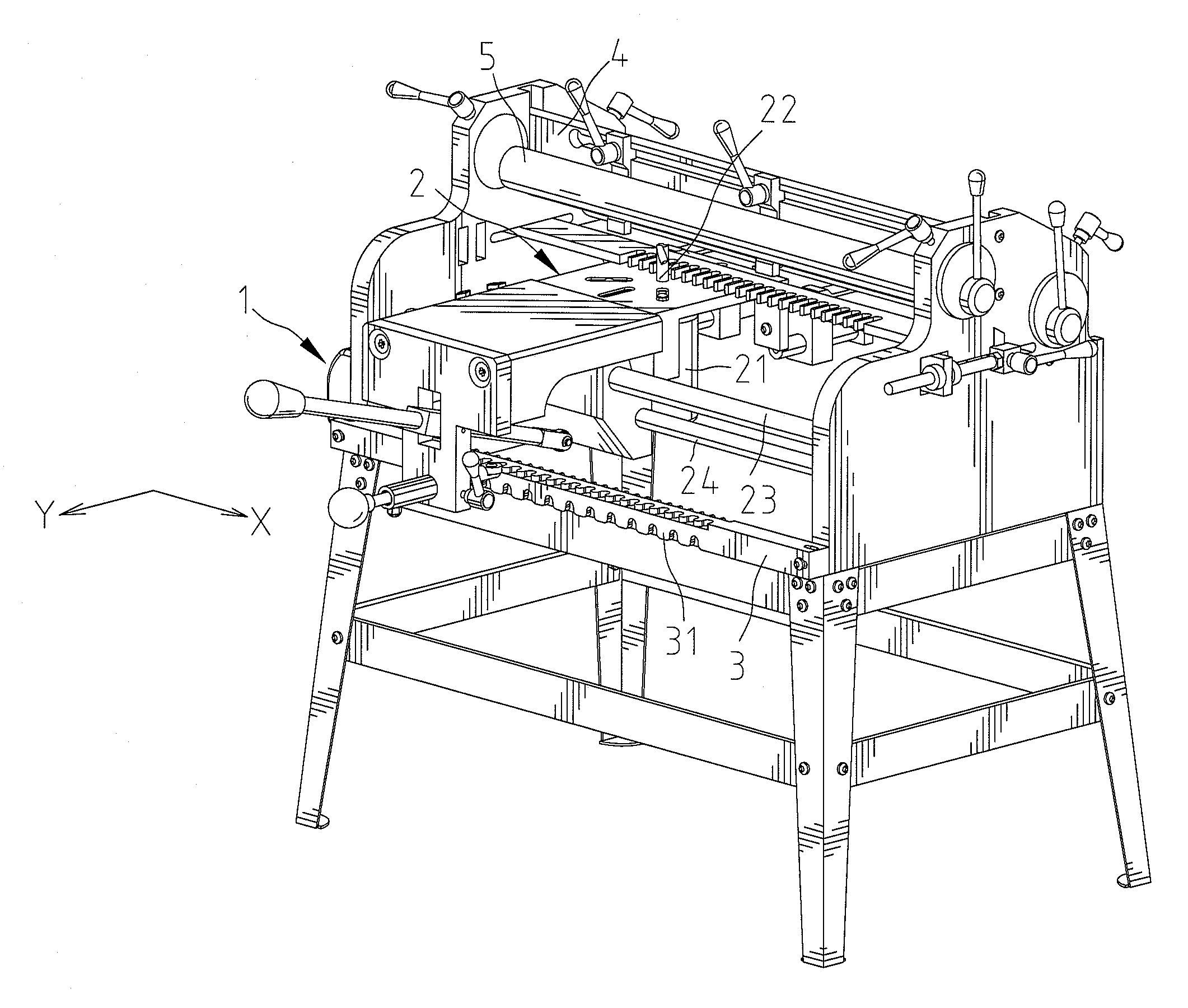
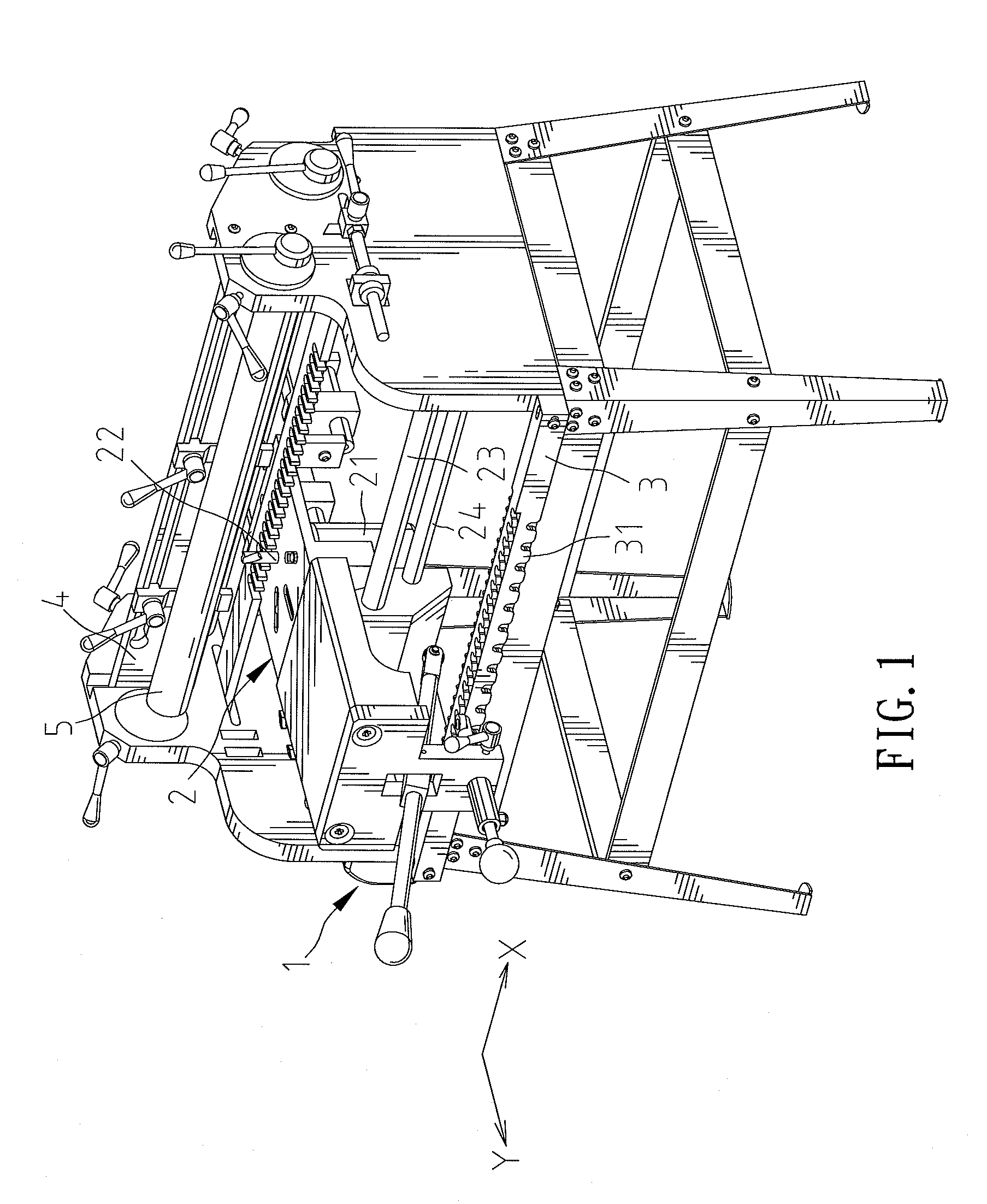
[0019]FIG. 1 shows a tenoner in accordance with the present invention. The tenoner includes an operation device 1, and a working device 2 connected and incorporated with the operation device 1. The working device 2 is movable in “X” direction and “Y” directions. In the preferred embodiment, the working device 2 is moved on rails 23 and 24 extending in “X” and “Y” directions, wherein the rail on the “Y” direction is not in view. Further, the working device 2 includes a motor 21 and a cutting bit 22 driven by the motor 21 for cutting tenons and / or mortises in a workpiece. The workpiece is clamped on a platform 4 during the working process. Further, the workpiece is securely held on the platform 4 by a cam structure 5. The tenoner also includes a guiding member 3 disposed axially in the direction of “X”. The guiding member 3 includes a plurality of sides, and each of the plurality of sides includes a plurality of protuberances 31 collectively defining an undulated edge. The undulated e...


PUM


Abstract

An operation device includes a connecting member mounted on and moved with a working device of a tenoner. A positioning mechanism is mounted on and moved with the connecting member and includes a tube mounted on the connecting member and adapted to be fixed at various positions, an elastic member and a shaft retained in a hollow of the tube. The shaft includes an end extended outside of the tube and a roller mounted on the end and engaged with a guiding member. The elastic member is disposed between the tube and the shaft and selectively depressed such that the elastic member enables the shaft to movably engage with an undulated edge of the guiding member in a quick and accurate manner.

Description

CROSS REFERENCE[0001]The present application is a continuation-in-part application of U.S. patent application Ser. No. 11 / 590,763, filed on Nov. 1, 2006, of which the entire disclosure is incorporated herein.BACKGROUND OF THE INVENTION[0002]1. Field of the Invention[0003]The present invention relates to an operation device and, in particular, to a device that facilitates a user to quickly and accurately displace a working device of a tenoner to manufacture a tenon and / or mortise during the working process.[0004]2. Description of the Related Art[0005]U.S. Pat. No. 6,929,042 entitled “SEMI-AUTOMATIC MORTISING MACHINE” shows a mortising machine including a support bar, a working device utilized to manufacture a tenon and / or a mortise in a workpiece, and a guide device movably mounted thereon for directing the working device to cut the workpiece. The support bar includes a plurality of protuberances collectively defining an undulated edge. The guide device includes a molding bar mounted...

Claims


Application Information

Patent Timeline
Patent Type & Authority Applications(United States)
IPC IPC(8): B27F1/00
CPCB27F1/12
Inventor YANG, JACK
Owner YANG JACK
Why Eureka
Try Eureka