Multi-antenna tire-pressure monitoring system with automatically positioning function

a technology of tire pressure monitoring and function, applied in the direction of antennas, antenna details, antennas, etc., can solve the problems of vehicle high risk of driving, inconvenient manual input method, and inability to use the z-axis sensor of the outside-type tire-pressure sensor in the pal method for positioning tires, etc., to achieve quick and accurate tire positioning, prevent errors, and improve safety.

Active Publication Date: 2022-07-28
SYSGRATION
View PDF7 Cites 1 Cited by
  • Summary
  • Abstract
  • Description
  • Claims
  • Application Information

AI Technical Summary

Benefits of technology

[0006]An objective of the present invention is to apply tire-pressure sensors to position tires by a quicker and more accurate manner, so as to solve the above-mentioned conventional technology drawbacks and problems.
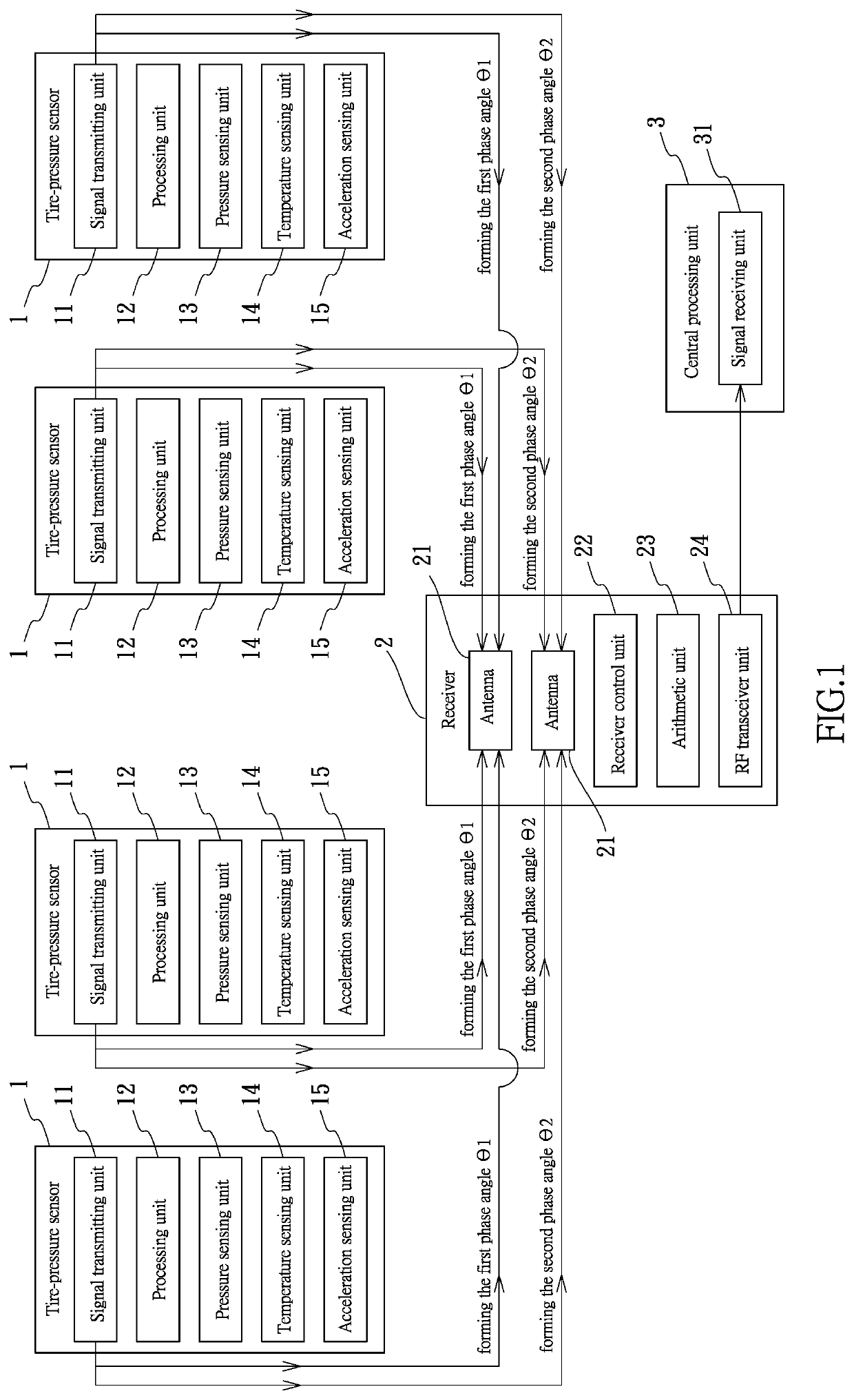
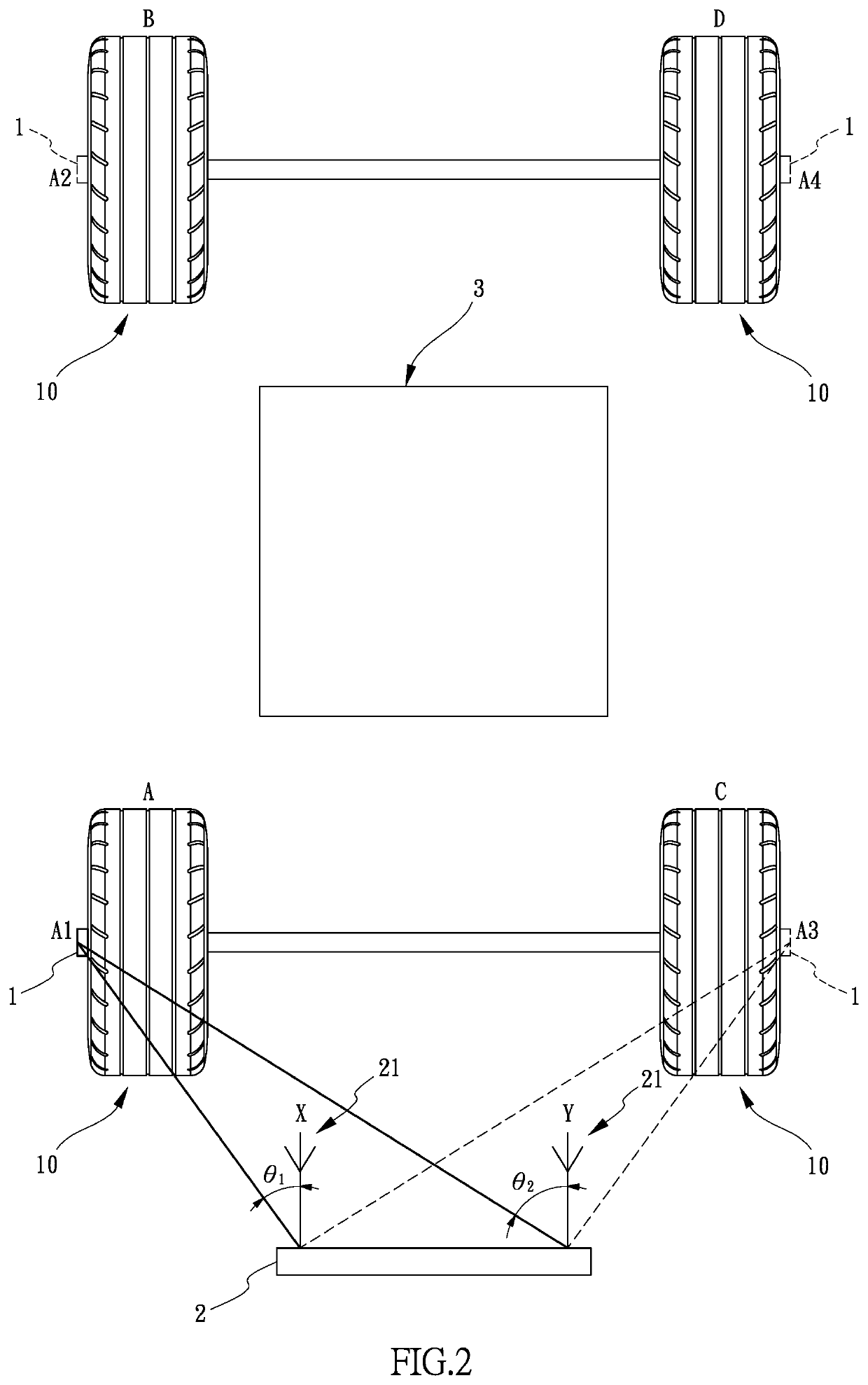
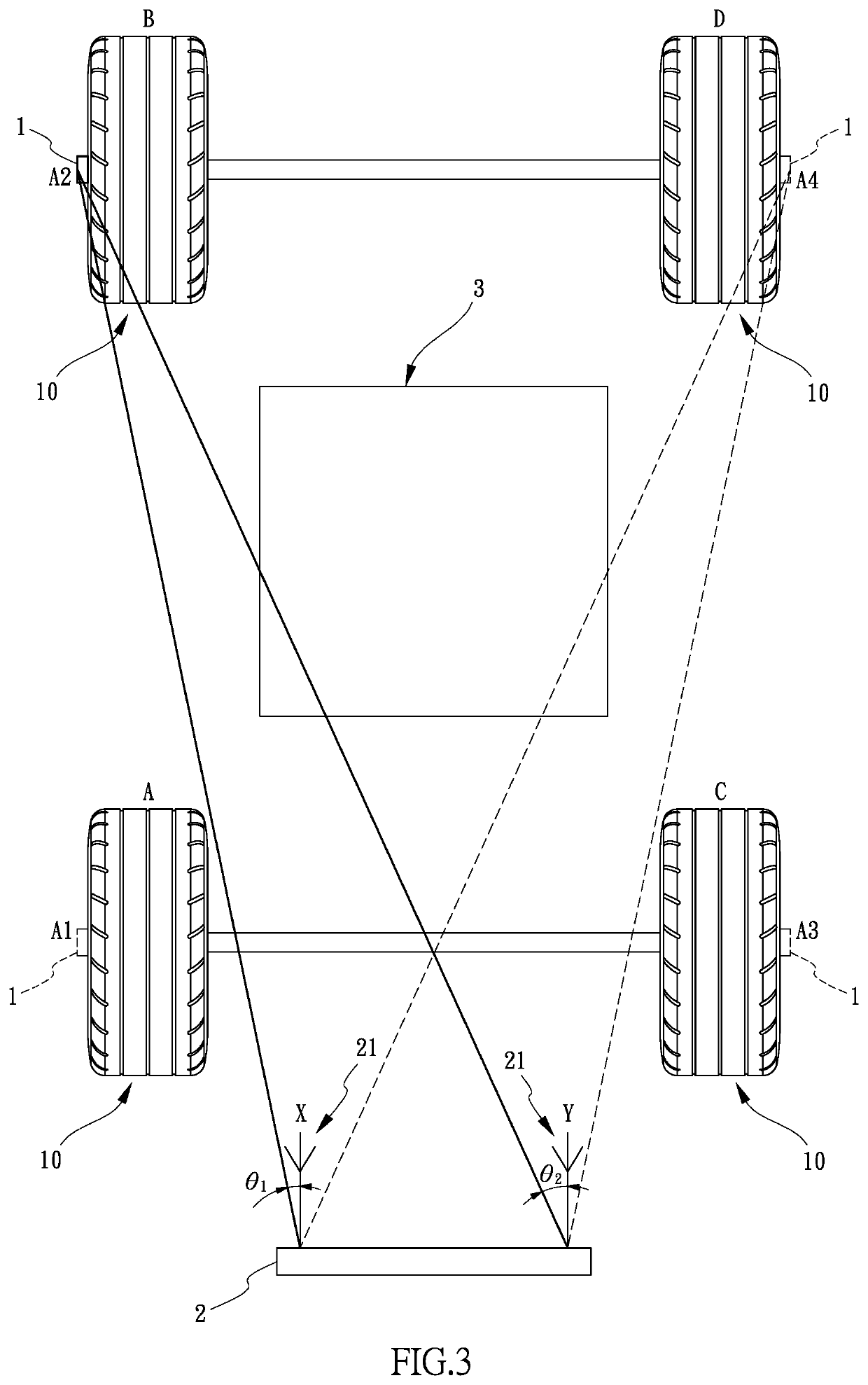
[0007]In order to achieve the objective, the present invention provides a multi-antenna tire-pressure monitoring system with automatically positioning function, and the multi-antenna tire-pressure monitoring system includes tire-pressure sensors, a receiver, and a central processing unit. The tire-pressure sensors are installed on tires of a vehicle, respectively, one of the tires is installed with at least one of the tire-pressure sensors, and each of the tire-pressure sensors includes a signal transmitting unit built therein. The receiver includes two antennas, and a receiver control unit built therein, wherein the two antennas are spaced by an interval and configured to receive signals transmitted from the tire-pressure sensors, a first phase angle and a second phase angle are formed between the signal transmitted from each of the tire-pressure sensors and the two antennas, respectively, wherein the receiver control unit receives the first phase angle and the second phase angle, and the arithmetic unit calculates phase-difference parameter values based on the first phase angle and the second phase angle, the receiver control unit calculates relative angles between the tire-pressure sensors and the receiver based on the phase-difference parameter values, to determine horizontal and longitudinal positions of the tires. The central processing unit includes a signal receiving unit built therein, and the signal receiving unit is configured to receive and display information calculated by the arithmetic unit of the receiver. The two antennas receive the signal transmitted from each of the tire-pressure sensors to form the first phase angle and the second phase angle, the arithmetic unit calculates a phase difference between the first phase angle and the second phase angle to form the phase-difference parameter value, the receiver control unit accurately determines the horizontal and longitudinal positions of the tires based on the phase-difference parameter values.
[0008]According to aforementioned contents that the two antennas are configured to obtain the first phase angle and the second phase angle of each tire-pressure sensors installed on each tire and the arithmetic unit calculates the phase differences to obtain the different phase-difference parameter values, and then calculates the relative angles between the tire-pressure sensors and the receiver based on the phase-difference parameter values, so as to determine the positions of the tires based on the relative angles. Therefore, the present invention has advantages of quickly precisely positioning the tires and preventing the error caused by manual input manner.

Problems solved by technology

Obviously, the manual input method is very inconvenient.
However, for outside-type tire-pressure sensors, the angles of valves are different and the rotation angles after assembly are not constant, so the data of the X-axis and Z-axis sensor of the outside-type tire-pressure sensor cannot be used in the PAL method for positioning the tires.
Therefore, if the tire-pressure sensor fails to accurately position the tires after the above-mentioned vehicle assembly process, the tire-pressure monitoring system may continuously detect the tire with error while the vehicle is driving, and it causes the vehicle to have a very high risk in driving.

Method used


Image

  • Multi-antenna tire-pressure monitoring system with automatically positioning function
  • Multi-antenna tire-pressure monitoring system with automatically positioning function
  • Multi-antenna tire-pressure monitoring system with automatically positioning function

Examples


Embodiment Construction

[0019]The following embodiments of the present invention are herein described in detail with reference to the accompanying drawings. These drawings show specific examples of the embodiments of the present invention. These embodiments are provided so that this disclosure will be thorough and complete, and will fully convey the scope of the invention to those skilled in the art. it is to be acknowledged that these embodiments are exemplary implementations and are not to be construed as limiting the scope of the present invention in any way. Further modifications to the disclosed embodiments, as well as other embodiments, are also included within the scope of the appended claims.

[0020]These embodiments are provided so that this disclosure is thorough and complete, and fully conveys the inventive concept to those skilled in the art. Regarding the drawings, the relative proportions and ratios of elements in the drawings may be exaggerated or diminished in size for the sake of clarity and...


PUM


Abstract

A multi-antenna tire-pressure monitoring system with automatically positioning function includes tire-pressure sensors, a receiver and a central processing unit. The tire-pressure sensors are installed on tires of a vehicle, respectively and each tire is installed with at least one tire-pressure sensor. Each tire-pressure sensor has a signal transmitting unit, the receiver includes two antennas and a built-in receiver control unit. A first phase angle and a second phase angle are formed between the signals transmitted from each tire-pressure sensor and the two antennas, the receiver control unit receives the first phase angle and the second phase angle, and the arithmetic unit calculates phase-difference parameter values, to determine the positions of the tires, the signal receiving unit built in the central processing unit receives and displays the information calculated by the arithmetic unit of the receiver, so as to complete positioning for the tires.

Description

BACKGROUND OF THE INVENTION1. Field of the Invention[0001]The present invention is related to a multi-antenna tire-pressure monitoring system with automatically positioning function and applied to a technology field of vehicle. The present invention mainly applies a difference in the phase angles between the tire-pressure sensor installed on the tire and the antennas to calculate relative angles, so as to accurately determine horizontal positions and longitude positions of the tires, and determine whether the positions of the tires are accurate.2. Description of the Related Art[0002]In recent years, traffic safety is taken seriously, so walking pedestrians or drivers must follow many traffic rules, and, new delivered vehicles and small trucks must be equipped with tire pressure monitoring systems (TPMS), in order to improve safety of pedestrian and ensure the stability of the vehicle at high speed.[0003]In the process of production and assembly, the vehicle factory installs tire-pre...

Claims


Application Information

Patent Timeline
Patent Type & Authority Applications(United States)
IPC IPC(8): B60C23/04H01Q1/32
CPCB60C23/0444H01Q1/3291B60C23/0416B60C23/0452B60C23/0437H01Q1/2241B60C23/0455B60C23/0488B60C23/0489
Inventor YU, CHIH-WEI
Owner SYSGRATION
Why Eureka
Try Eureka