Stator for rotary electric machine

a technology of rotary electric machines and stabilizers, which is applied in the direction of dynamo-electric machines, electrical apparatus, windings, etc., can solve the problems of wedge members achieve the effects of preventing the wedge members from being bent or folded, facilitating the inserting of wedge members into the slots, and enhancing the rigidity and strength of the wedge members

Active Publication Date: 2009-11-26
SANYO DENKI CO LTD
View PDF8 Cites 49 Cited by
  • Summary
  • Abstract
  • Description
  • Claims
  • Application Information

AI Technical Summary

Benefits of technology

[0017]A stator for a rotary electric machine according to the present invention may not necessarily include a continuous coupling portion or a coupling portion. In this configuration, the plurality of wedge members may be integrally formed of a synthetic resin material, a pair of gaps may be formed between the magnetic pole surface forming portion of each magnetic pole portion and an opposed portion of the slot insulator that faces the magnetic pole surface forming portion; one of the gaps may communicate with the slot formed adjacent to the magnetic pole portion on one side in the circumferential direction and the other one of the gaps may communicate with the slot formed adjacent to the magnetic pole portion on the other side in the circumferential direction, and an end portion of the block portion of each wedge member inserted into the slot may be fitted into the gap adjacent to the end portion of the block portion. Also in this configuration, the wedge members may be prevented from being bent or folded when they are inserted into the slots, and the wedge members may securely be held in position in the slots.
[0018]The slot insulator may be formed with a plurality of grooves for receiving free ends of the partition wall portions of the plurality of wedge members. In this way, the wedge members may further be securely held in position in the slots.
[0019]Since the coupling portion is integrally formed with the wedge member in the present invention, the coupling portion reinforces the wedge member to enhance the rigidity and strength of the wedge member. Thus, the wedge members may be prevented from being bent or folded when they are inserted into the slots as in the related art. Moreover, inserting the wedge members into the slots may be facilitated by the use of the coupling portion.

Problems solved by technology

In the conventional stator for a rotary electric machine, however, the wedge members may be bent or folded when they are inserted into the slots one by one.

Method used


Image

  • Stator for rotary electric machine
  • Stator for rotary electric machine
  • Stator for rotary electric machine

Examples


Embodiment Construction

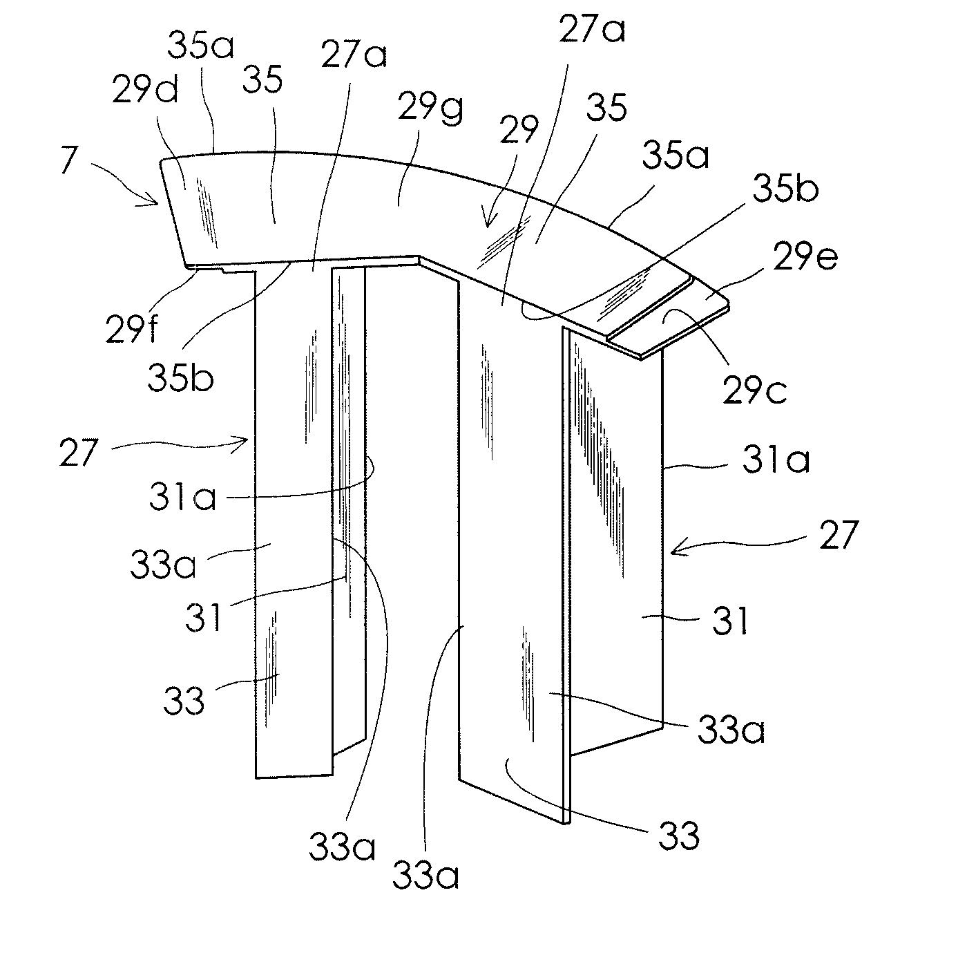
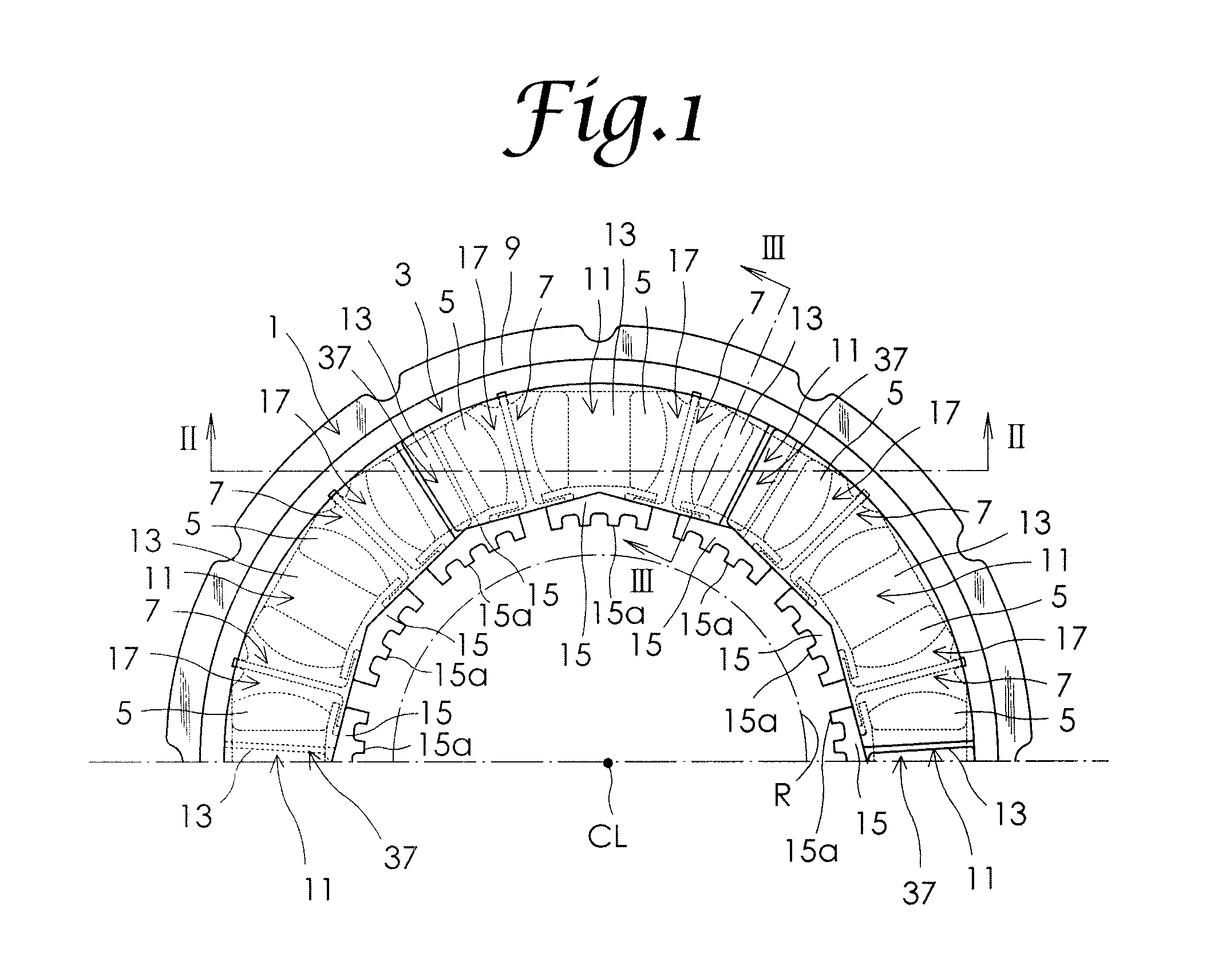
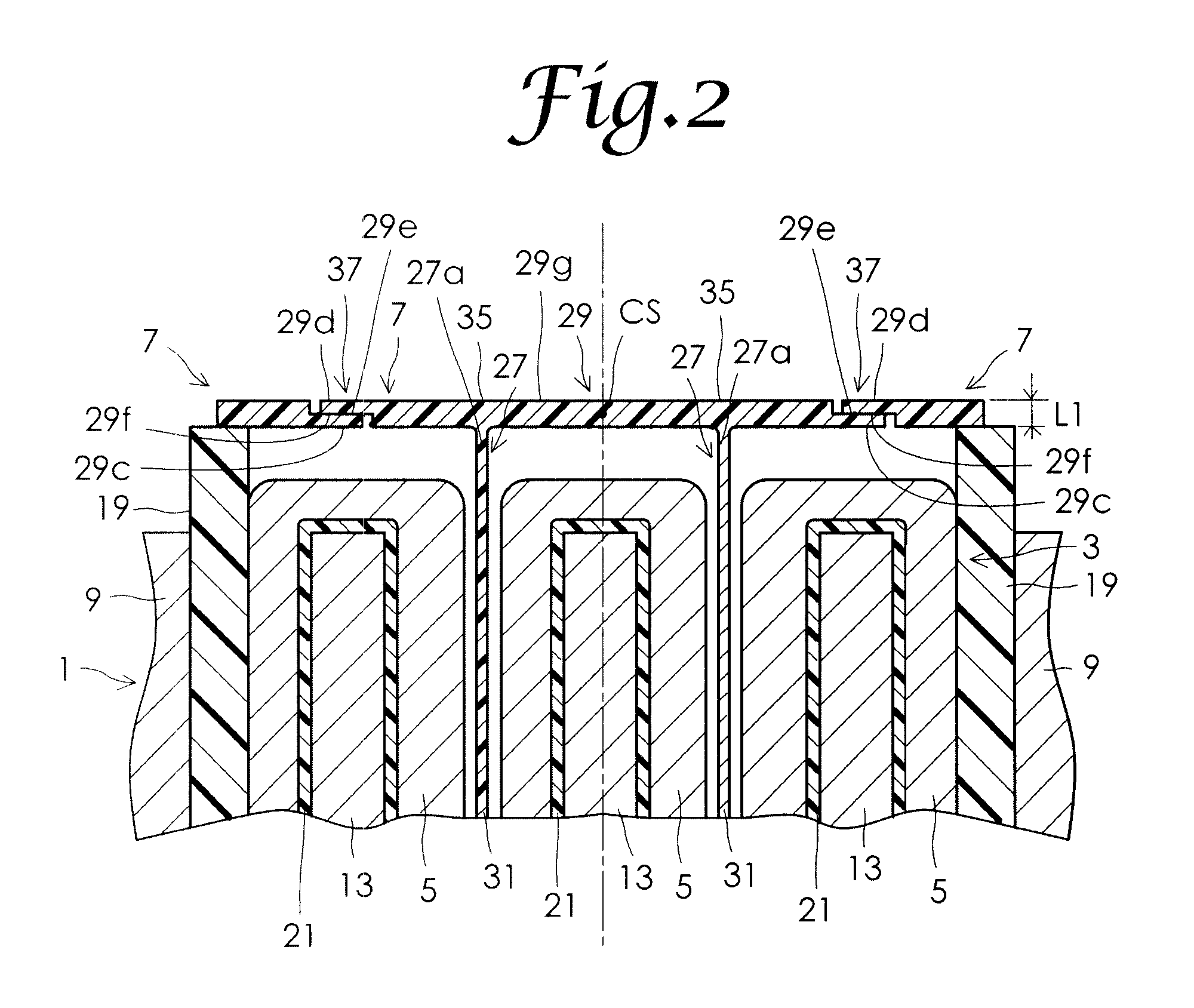
[0030]Hereinafter, a stator for a rotary electric machine according to an embodiment of the present invention will be described in detail with reference to the drawings. FIG. 1 is a plan view of a part of a stator for a rotary electric machine according to this embodiment. FIG. 2 is a cross-sectional view taken along line II-II of FIG. 1. FIG. 3 is a cross-sectional view taken along line III-III of FIG. 1. FIG. 4 is a partial enlarged view of FIG. 1. For ease of understanding, a continuous coupling portion 29 of a wedge structural unit 7 to be discussed later is not illustrated in FIG. 4. As shown in the figures, the stator for a rotary electric machine according to this embodiment includes a stator core 1, a slot insulator 3, a plurality of winding portions 5, and a plurality of wedge structural units 7. The stator core 1 includes an annular yoke 9 and a plurality of magnetic pole portions 11 disposed radially inwardly of the yoke 9 at intervals in the circumferential direction of ...


PUM


Abstract

A stator for a rotary electric machine with wedge members insertable into slots without being bent or folded is provided. A coupling portion is integrally formed at a non-inserted end portion, which is not inserted into a slot, of a wedge member, the coupling portion extending across an end of a partition wall portion and an end of a block portion. The wedge member and the coupling portion are formed of a synthetic resin material. Two or more coupling portions of two or more adjacently disposed wedge members are integrally formed as a continuous coupling portion.

Description

BACKGROUND OF THE INVENTION[0001]1. Field of the Invention[0002]The present invention relates to a stator for use in a rotary electric machine such as a motor.[0003]2. Description of the Related Art[0004]In general, a stator for a rotary electric machine includes a stator core, a slot insulator made of a synthetic resin and fitted to the stator core, and a plurality of winding portions. The stator core for a rotary electric machine includes an annular yoke and a plurality of magnetic pole portions disposed radially inwardly of the yoke at intervals in a circumferential direction of the yoke. The magnetic pole portions each have a pole column with an outer end portion connected to an inner periphery of the yoke and a magnetic pole surface forming portion provided at an inner end portion of the pole column and including a magnetic pole surface facing a rotor of the rotary electric machine. The winding portions are formed by concentratedly winding a winding conductor around the pole co...

Claims


Application Information

Patent Timeline
Patent Type & Authority Applications(United States)
IPC IPC(8): H02K3/487H02K3/34
CPCH02K3/487
Inventor TAKESHITA, IKUOMIYAIRI, SHIGENORI
Owner SANYO DENKI CO LTD
Why Eureka
Try Eureka