Wireless charging module and electronic apparatus

Inactive Publication Date: 2009-11-26
DARFON ELECTRONICS CORP
View PDF4 Cites 228 Cited by
  • Summary
  • Abstract
  • Description
  • Claims
  • Application Information

AI Technical Summary

Benefits of technology

[0007]The invention is directed to a wireless charging module and an electronic apparatus that can be charged via a wireless path, wherein the wireless charging module charges the electronic apparatus via energy coupling between resonators. Compared with the conventi

Problems solved by technology

Thus, the user cannot operate the wireless electronic apparatus in a wireless manner s

Method used


Image

  • Wireless charging module and electronic apparatus
  • Wireless charging module and electronic apparatus
  • Wireless charging module and electronic apparatus

Examples


first embodiment

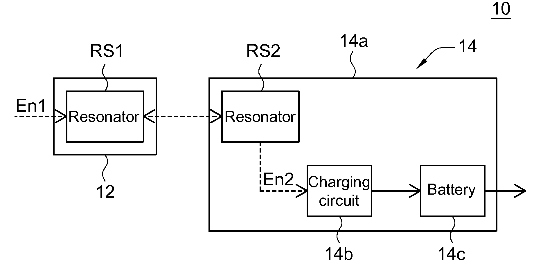
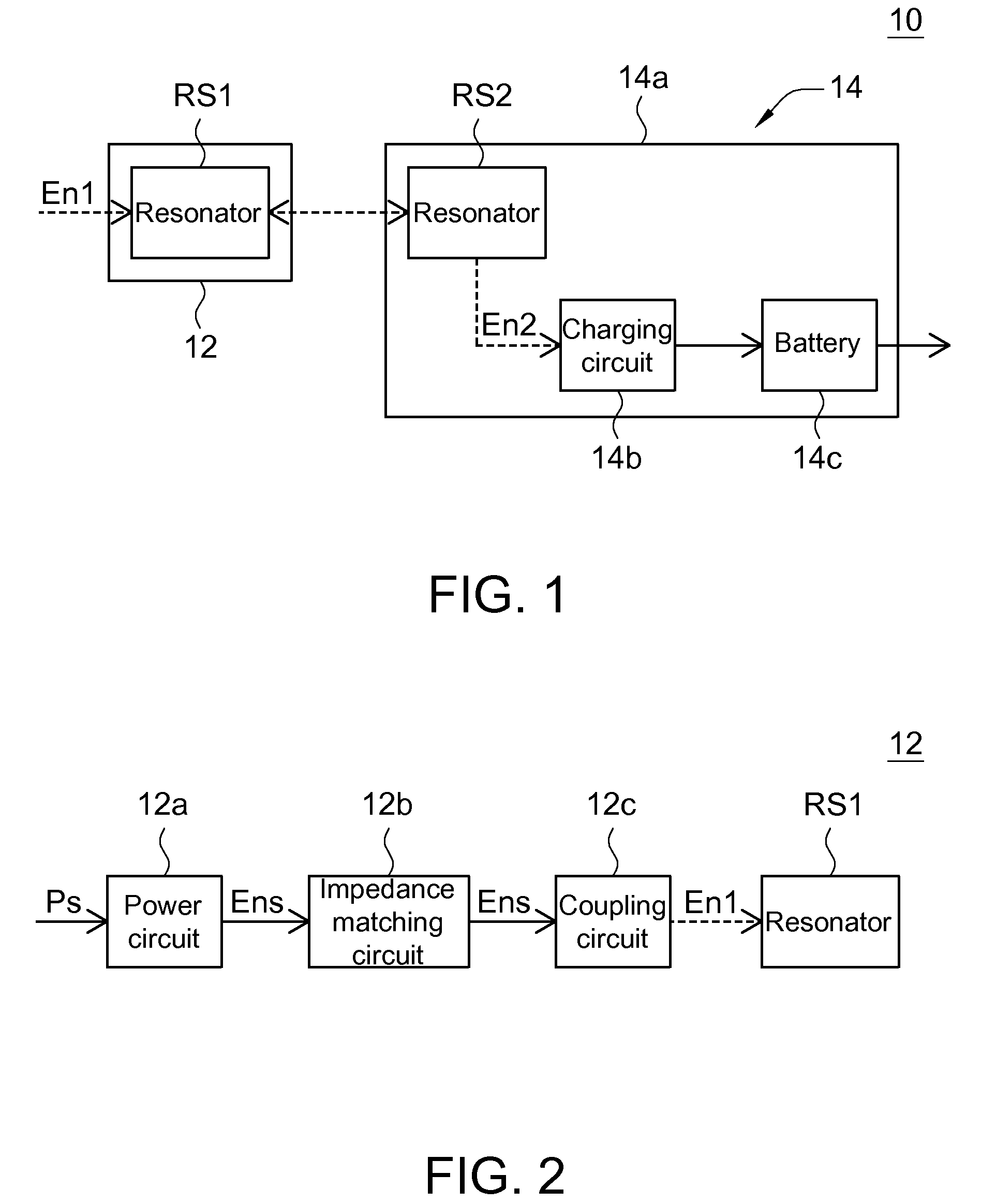
[0025]The wireless charging module of this embodiment provides electric energy to a wireless receiving module via a wireless power supplying module so as to charge a battery of the wireless receiving module in a wireless manner. FIG. 1 is a block diagram showing a wireless charging module 10 according to a first embodiment of the invention. Referring to FIG. 1, the wireless charging module 10 includes a wireless power supplying module 12 and a wireless receiving module 14. The wireless power supplying module 12 includes a resonator RS1, having a resonance frequency fo1, for receiving electric energy En1.

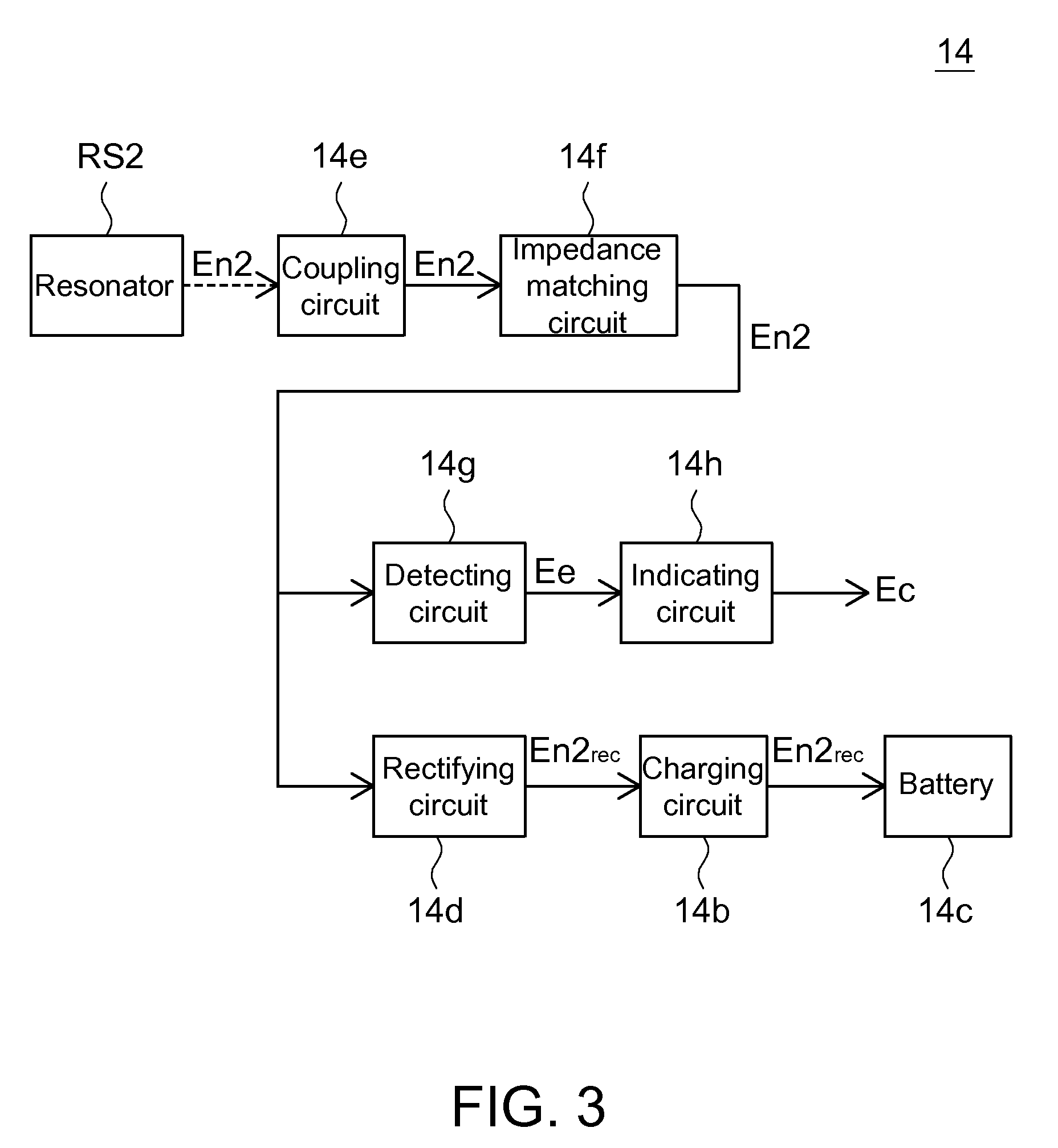
[0026]The wireless receiving module 14 includes a body 14a, a charging circuit 14b, a resonator RS2, and a battery 14c. The body 14a is electrically connected to the battery 14c. The resonator RS2 is electrically connected to the body 14a and has a resonance frequency fo2 substantially the same as the resonance frequency fo1. The electric energy En1 of the resonator RS1 is coupled to...

second embodiment

[0038]The wireless receiving module of the wireless charging module according to this embodiment includes a shell, and the resonator of the wireless receiving module is located on an inner wall of the shell. FIG. 5A is a schematic illustration showing a wireless receiving module 24 according to a second embodiment of the invention. FIG. 5B is a cross-sectional view taken along a line AA′ of FIG. 5A. Referring to FIGS. 5A and 5B, the difference between the wireless receiving module 24 of this embodiment and the wireless receiving module 14 of the first embodiment is that the wireless receiving module 24 of this embodiment further has a shell 24s, and the resonator located inside the wireless receiving module 24 is a solenoid conductor coil.

[0039]The coil in the solenoid conductor coil is located on the inner wall of the shell 24s in a manner of surrounding the inner wall of the shell 24s. More specifically, the solenoid conductor coil includes multiple coil bodies. The inner wall of ...

third embodiment

[0040]The wireless charging module of this embodiment includes an electronic apparatus, which may be disposed in a manner separable from the wireless receiving module of the wireless charging module. The wireless power supplying module of the wireless charging module provides the electric energy to drive the electronic apparatus via the wireless receiving module. FIG. 6 is a block diagram showing a wireless charging module 20 according to a third embodiment of the invention. As shown in FIG. 6, the difference between the wireless charging module 20 of this embodiment and the wireless charging module 10 of the first embodiment is that the wireless charging module 20 further includes an electronic apparatus 26, which may be disposed in a manner separable from the wireless receiving module 24. The electronic apparatus 26 is connected to the wireless receiving module 24 via a power line PL.

[0041]The electronic apparatus 26 includes a body 26a, a charging circuit 26b, a battery 26c, and ...


PUM


Abstract

A wireless charging module includes a wireless power supplying module and a wireless receiving module. The wireless power supplying module includes a first resonator, which is for receiving first electric energy and has a first resonance frequency. The wireless receiving module includes a body, a shell, a second resonator and a charging circuit. The body is electrically connected to a battery. The second resonator is located on an inner wall of the shell and is electrically connected to the body. The second resonator has a second resonance frequency substantially the same as the first resonance frequency. The first electric energy of the first resonator is coupled to the second resonator so that non-radiative energy transfer is performed between the first and second resonators. The second resonator provides second electric energy. The charging circuit receives the second electric energy to charge the battery.

Description

[0001]This application claims the benefit of Taiwan application Serial No. 097118491, filed May 20, 2008, the subject matter of which is incorporated herein by reference.BACKGROUND OF THE INVENTION[0002]1. Field of the Invention[0003]The invention relates in general to a wireless charging module, and more particularly to a wireless charging module for supplying energy to an electronic apparatus via energy coupling between resonators.[0004]2. Description of the Related Art[0005]In the modern age, in which the technology changes with each passing day, humans have used to make their life become more conveniently by widely using various electronic apparatuses. Conventionally, an electronic apparatus needs a power module to provide the electric energy required in operating the electronic apparatus. In one example, the wireless electronic apparatus is provided with a battery to power the wireless electronic apparatus. When the electric energy of the battery is used up, the user electrical...

Claims


Application Information

Patent Timeline
IPC IPC(8): H02J7/00H02J50/12
CPCH02J7/025H02J50/12H02J7/0047H02J7/00
Inventor CHEN, CHIH-JUNGLIN, CHIH-LUNGHSU, CHENG-CHIEH
Owner DARFON ELECTRONICS CORP
Why Eureka
Try Eureka