
Peer to peer surveillance architecture

Active Publication Date: 2009-11-26
LEVERAGE INFORMATION SYST INC
View PDF16 Cites 102 Cited by
  • Summary
  • Abstract
  • Description
  • Claims
  • Application Information

AI Technical Summary

Benefits of technology

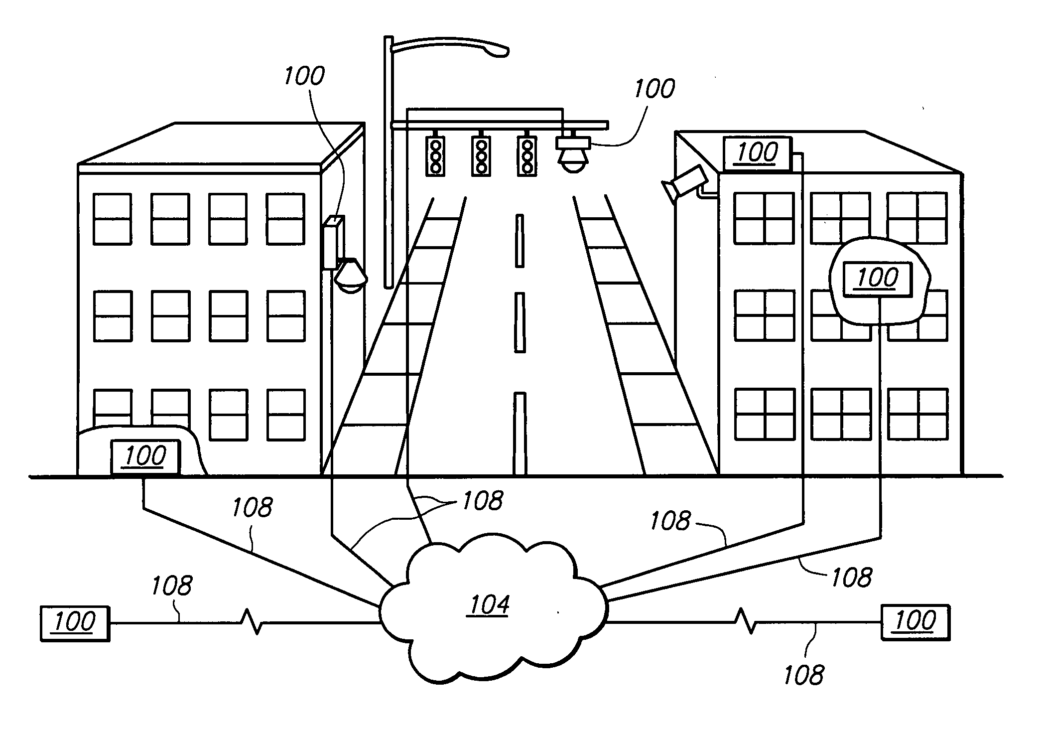
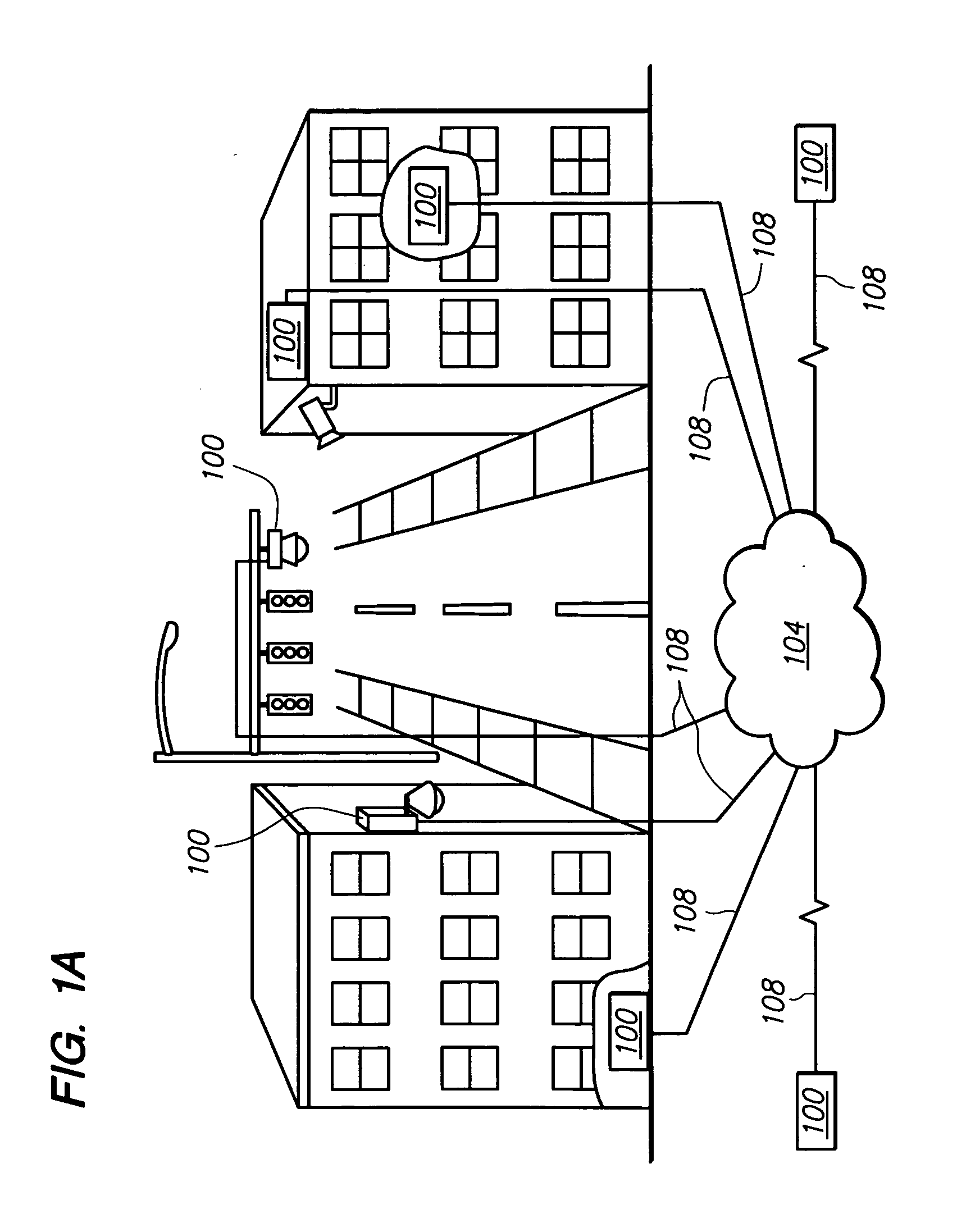
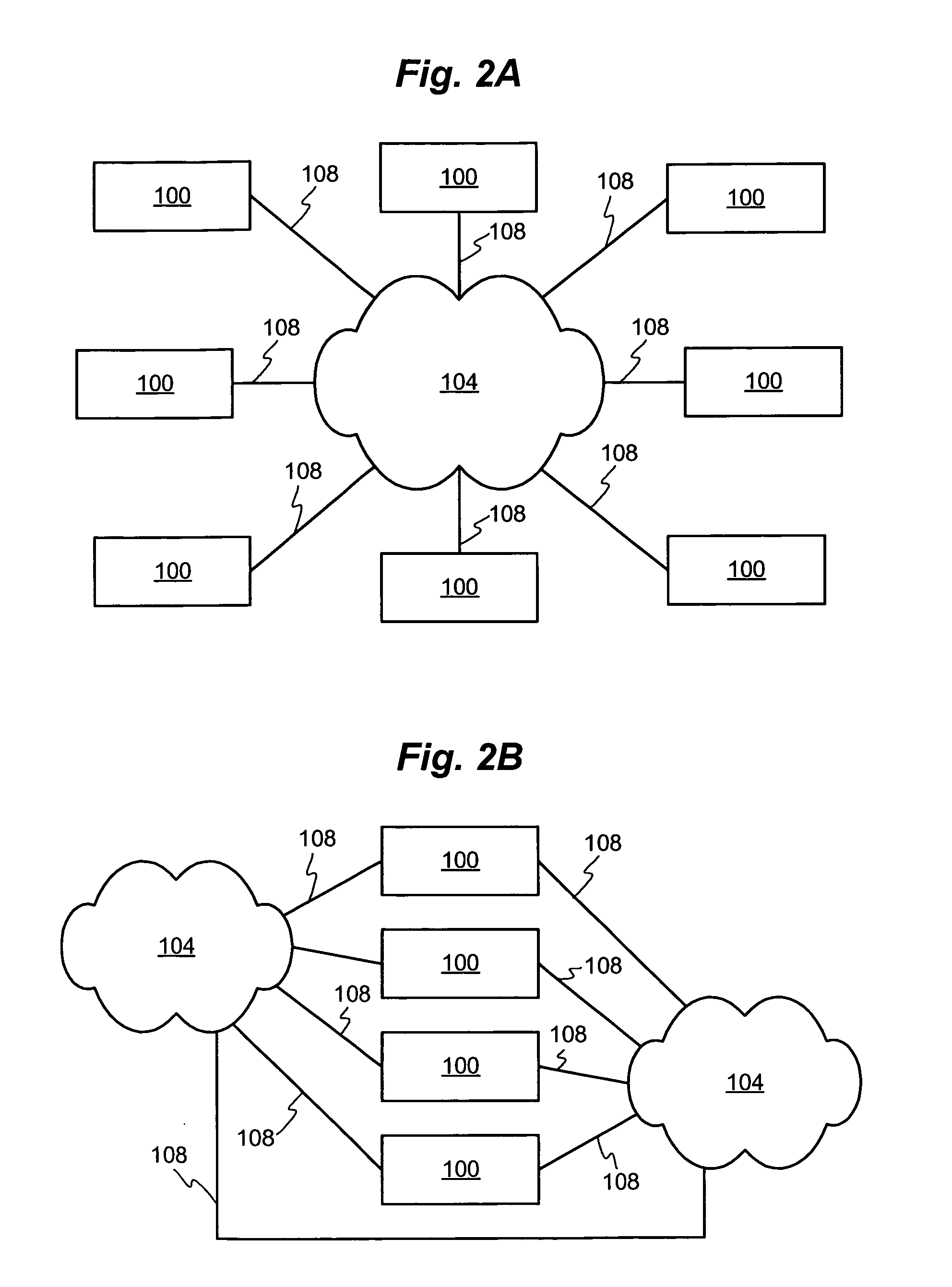
[0012]A peer to peer surveillance architecture comprising a plurality of peer to peer nodes is disclosed. In one embodiment, one or more of the peer to peer nodes are capture nodes having one or more capture devices, server nodes configured to authenticate access to surveillance information, and viewing nodes having at least one screen. T

Problems solved by technology

However, this introduces a single point of failure in that the failure of the central controller would render the entire surveillance system inoperative.
Thus, such systems are said to be fragile as a failure of the central controller or the connections between the controller and the cameras either impairs or completely prevents the surveillance system from functioning.
This fragility is highly undesirable in a surveillance system especially where public safety is concerned.
In addition, digital video may be sent across vast distances through digital networks, such as the Internet, which was not possible without great expense using traditional CCTV systems.
Thus, the single point of failure has remained through the transition from traditional CCTV and similar systems to network based surveillance systems.
While these backup systems provide increased reliability they do so at increased cost and often do not provide a seamless transition from the failed equipment to its associated backup device.
In surveillance, any downtime including downtime associated with switching to a backup device is highly undesirable.
Traditional systems are also difficult to update for new circumstances or environments.
These connections are often physical connections, such as network or coaxial cabling, which are difficult to install especially in existing structures.

Method used


Image

  • Peer to peer surveillance architecture
  • Peer to peer surveillance architecture
  • Peer to peer surveillance architecture

Examples


Embodiment Construction

[0035]In the following description, numerous specific details are set forth in order to provide a more thorough description of the present invention. It will be apparent, however, to one skilled in the art, that the present invention may be practiced without these specific details. In other instances, well-known features have not been described in detail so as not to obscure the invention.

[0036]Generally, the peer to peer surveillance architecture comprises one or more nodes configured to capture, analyze, store, and present surveillance information. As discussed further below, surveillance information comprises a wide variety of information including video and audio. As used herein, peer to peer means that each node within the surveillance architecture operates such that it is not dependent on (i.e. does not rely on) its peer nodes. This allows the surveillance architecture to have no single point of failure making it extremely robust. The failure of or damage to individual nodes, ...


PUM


Abstract

A peer to peer surveillance architecture comprising a plurality of independent nodes for capturing, analyzing, storing, and viewing surveillance information is disclosed. The surveillance architecture has no central controller or single point of failure because of the peer to peer or independent relationship between its nodes. Generally, surveillance information of various types is captured by one or more capture nodes and transmitted to or one or more viewing, content storage, or server nodes for display, analysis, storage, or a combination thereof. Server nodes may provide authentication services to validate user or device credentials prior to granting access to surveillance information. In one or more embodiments, specialized video compression hardware is provided to allow high quality video surveillance information to be transmitted across low bandwidth connections. Compression may also be performed on other types of surveillance information.

Description

BACKGROUND OF THE INVENTION[0001]1. Field of the Invention[0002]The invention relates to surveillance systems, particularly to a peer to peer surveillance architecture capable of capturing and providing video, audio, and other information.[0003]2. Related Art[0004]Surveillance is widely utilized in modern society. Governments, corporations, groups, and even individuals use surveillance to promote public safety and to deter and prevent crime as well as for general monitoring.[0005]Traditional surveillance systems generally provide audio and video monitoring through an interconnected hierarchical system. For example, a closed-circuit television (CCTV) system may provide video monitoring through a set of closed-circuit cameras connected to a single stand alone aggregation device where the video feeds from the cameras are sent. The captured information may then be viewed through the aggregation device such as on one or more video screens.[0006]To function properly, a CCTV or other simil...

Claims


Application Information

Patent Timeline
IPC IPC(8): H04N7/18G08B21/00
CPCH04N7/18H04N7/181
Inventor LEBLOND, RAYMOND G.
Owner LEVERAGE INFORMATION SYST INC
Learn More