
Removal of bitumen from slurry using a scavenging gas

a technology of slurry and bitumen, applied in the direction of liquid hydrocarbon mixture production, water/sludge/sewage treatment, centrifugal force sediment separation, etc., can solve the problems of difficulty in extracting bitumen from slurry, difficulty in scaling up,

Inactive Publication Date: 2009-12-03
KRUYER JAN
View PDF0 Cites 8 Cited by
  • Summary
  • Abstract
  • Description
  • Claims
  • Application Information

AI Technical Summary

Benefits of technology

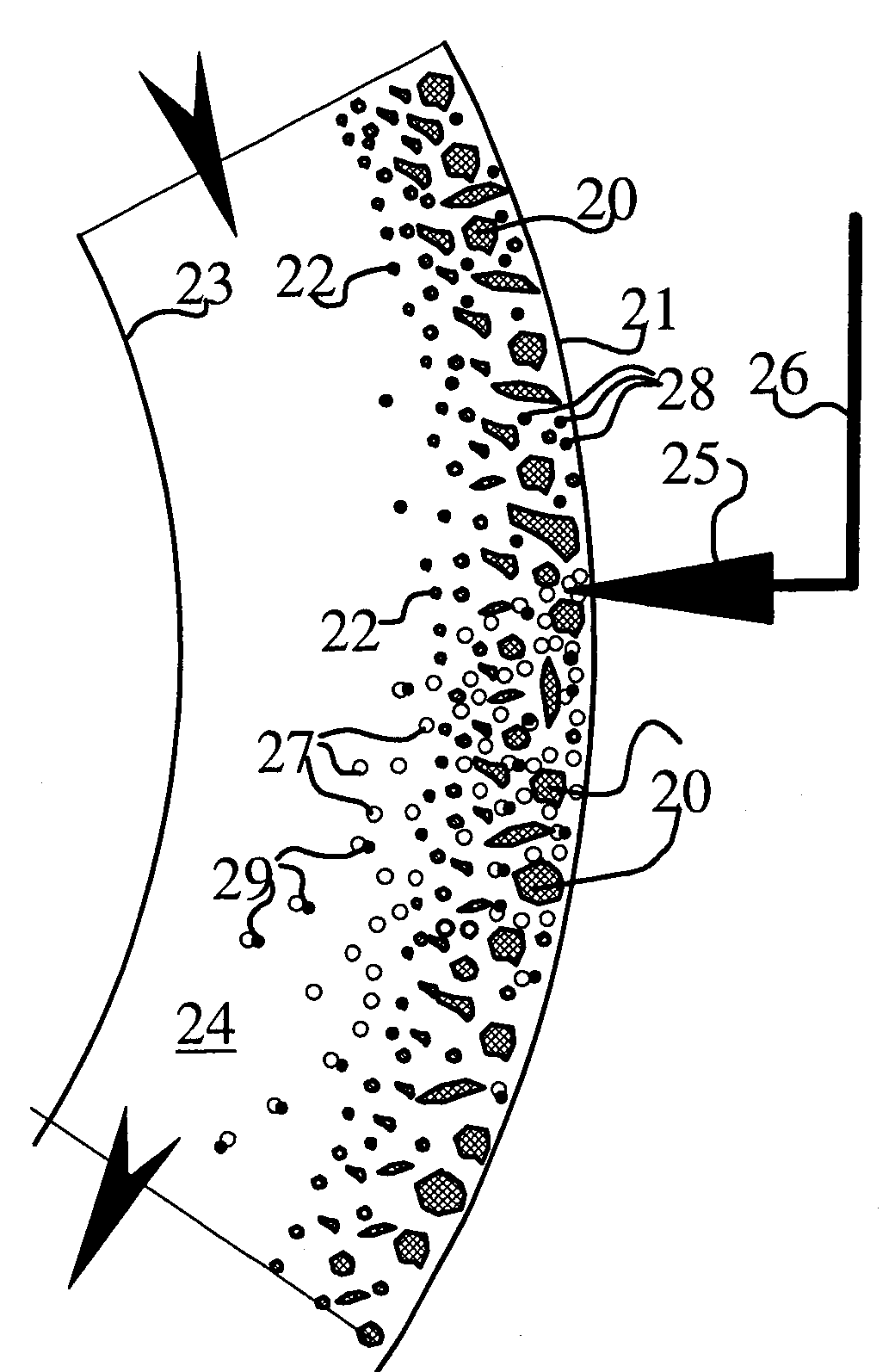
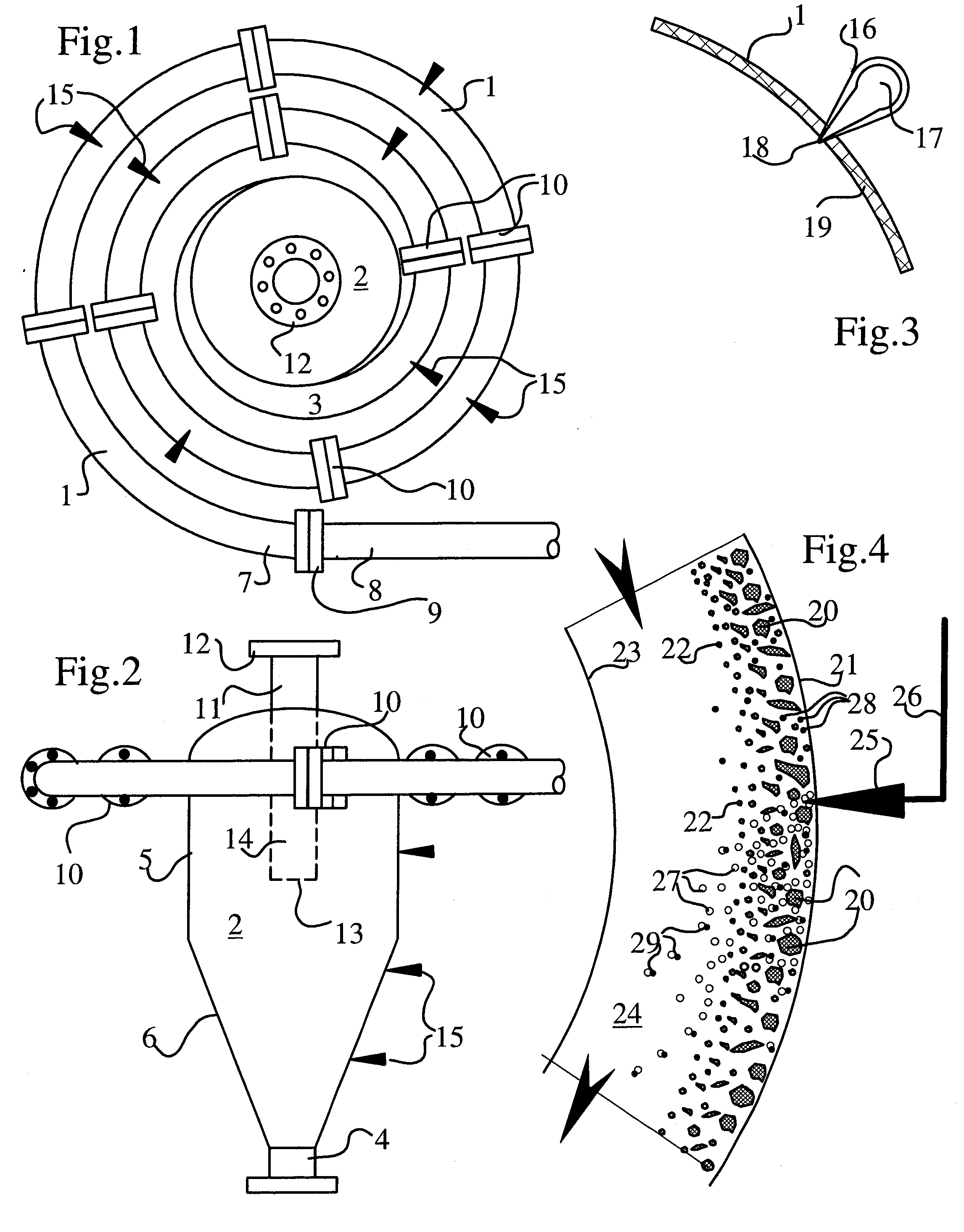
The present invention relates to a hydrocyclone and a related method for separating components from a fluid or oil sand slurry. The hydrocyclone can be used to de-sand the slurry by using a continuous water phase to separate bitumen from sand particles. The hydrocyclone includes a helical confined path connected to an open cylindrical vessel, which allows the fluid to rotate along a swirl path within the vessel. The rotation along the swirl path produces an overflow and an underflow. A rinse fluid can be injected to remove the underflow. The invention also includes a method for scavenging bitumen droplets from the slurry using small bubbles of gas. The technical effects of the invention include improved separation of bitumen from sand particles and efficient removal of bitumen droplets from the slurry.

Problems solved by technology

Oil sands resources are relatively untapped.
Perhaps the largest reason for this is the difficulty of extracting bitumen from the sands.
There were a number of drawbacks, though, to the Kruyer process.
One drawback to the Kruyer process is related to the art of scaling up.

Method used


Image

  • Removal of bitumen from slurry using a scavenging gas
  • Removal of bitumen from slurry using a scavenging gas

Examples


Embodiment Construction

[0021]Before the present invention is disclosed and described, it is to be understood that this invention is not limited to the particular structures, process steps, or materials disclosed herein, but is extended to equivalents thereof as would be recognized by those ordinarily skilled in the relevant arts. It should also be understood that terminology employed herein is used for the purpose of describing particular embodiments only and is not intended to be limiting.

[0022]It must be noted that, as used in this specification and the appended claims, the singular forms “a,”“an,” and “the” include plural referents unless the context clearly dictates otherwise. Thus, for example, reference to “a pump” includes one or more of such pumps, reference to “an elbow” includes reference to one or more of such elbows, and reference to “injecting” includes reference to one or more of such actions.

[0023]Definitions

[0024]In describing and claiming the present invention, the following terminology w...


PUM

PropertyMeasurementUnit
temperaturesaaaaaaaaaa
diameteraaaaaaaaaa
diameteraaaaaaaaaa

Abstract

A separating apparatus can be used for separating components of a fluid. The apparatus can include a substantially open cylindrical vessel and a helical confined conduit connected upstream of the cylindrical vessel. The open vessel can include an open vessel inlet configured to introduce a fluid tangentially into the open vessel. The helical confined conduit can be connected to the open vessel at the open vessel inlet. A series of gas nozzles can be used to introduce gas bubbles into the helical confined path and / or the open vessel which draw bitumen from an outer flow region to an inner flow region of the slurry. An overflow outlet and underflow outlet can be operatively attached to the open vessel for removal of the separated fluid components. Although a number of fluids can be effectively treated, de-sanding of bitumen slurries from oil sands can be readily achieved.

Description

RELATED APPLICATIONS[0001]This application is related to U.S. patent application Ser. No. 11 / 940,099 entitled “Hydrocyclone and Associated Methods,” filed on Nov. 14, 2007 and to U.S. patent application Ser. No. 11 / 939,978 entitled “Sinusoidal Mixing and Shearing Apparatus and Associated Methods,” filed on Nov. 14, 2007 which are incorporated herein by reference.FIELD OF THE INVENTION[0002]The present invention relates to devices and methods for hydraulically sorting of fluids after these have been processed by static mixing and / or shearing of fluids, or by other methods. Accordingly, the present invention involves the fields of process engineering, chemistry, and chemical engineering.BACKGROUND OF THE INVENTION[0003]According to some estimates, oil sands, also known as tar sands or bituminous sands, may represent up to two-thirds of the world's petroleum. Oil sands resources are relatively untapped. Perhaps the largest reason for this is the difficulty of extracting bitumen from th...

Claims


Application Information

Patent Timeline
Patent Type & Authority Applications(United States)
IPC IPC(8): C02F1/24C02F1/38C02F103/10
CPCB03B9/02B03D1/1418B04C1/00B03D1/242B04C7/00B04C2009/008C10G1/04B04C5/04
Inventor KRUYER, JAN
Owner KRUYER JAN
Learn More