Servo signal recording apparatus, information recording apparatus, and tracking servo method

Active Publication Date: 2009-12-03
FUJIFILM CORP
View PDF6 Cites 11 Cited by
  • Summary
  • Abstract
  • Description
  • Claims
  • Application Information

AI Technical Summary

Benefits of technology

[0017]The present invention enables periodic noise and narrow-band noise to be removed from the position error

Problems solved by technology

When the recording track width is reduced by employing a high recording density technique for magnetic tape, the magnetic head is unable to accurately follow the recording track due to the lateral motion of the magnetic tape during data recording or reproduction, or the like.
If the magnetic head is unable to accurately follow the recording track, errors are more likely to occur in writing information to the magnetic tape or in recording information from the magnetic tape.
However, a p

Method used


Image

  • Servo signal recording apparatus, information recording apparatus, and tracking servo method
  • Servo signal recording apparatus, information recording apparatus, and tracking servo method
  • Servo signal recording apparatus, information recording apparatus, and tracking servo method

Examples


embodiment 1

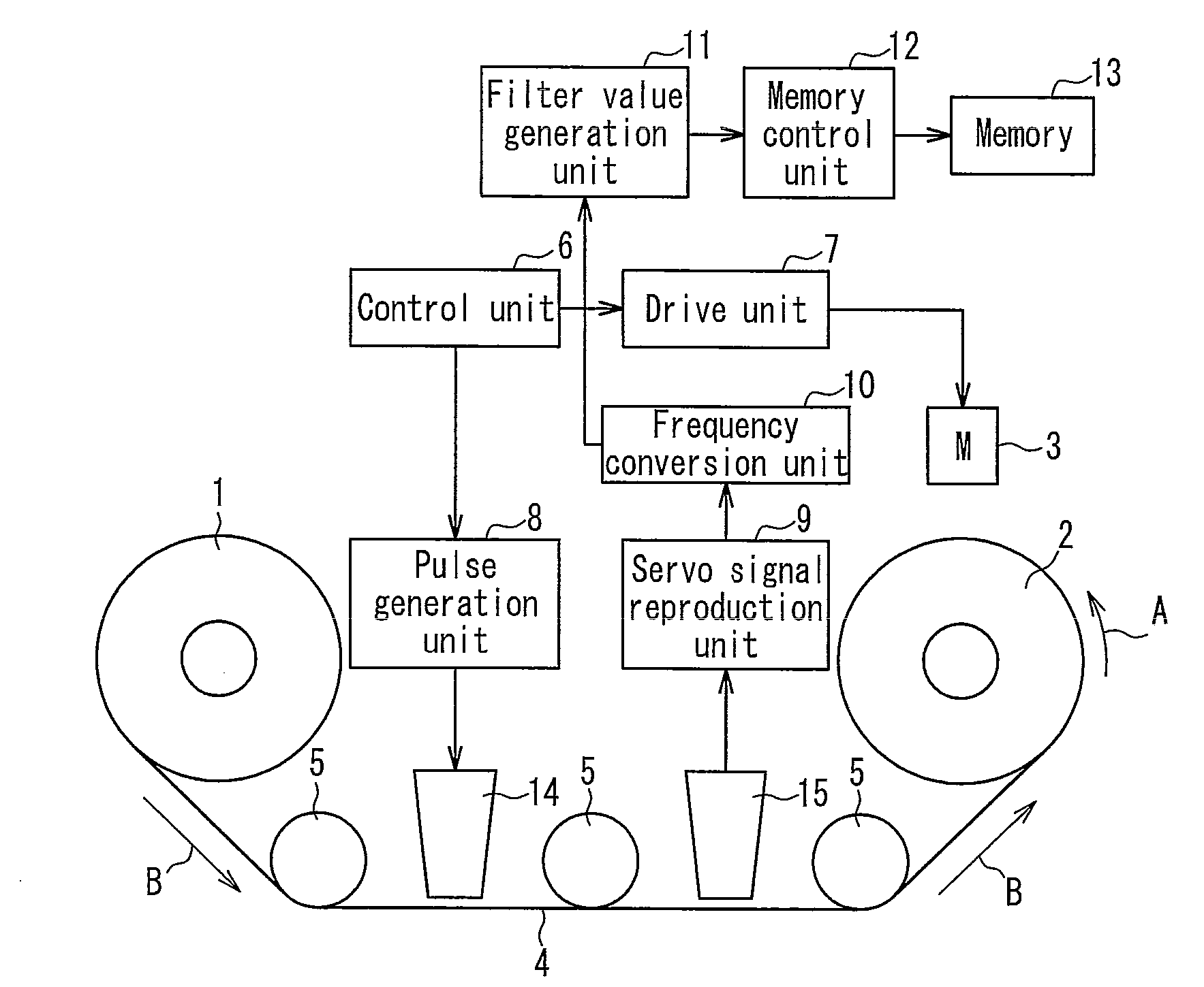
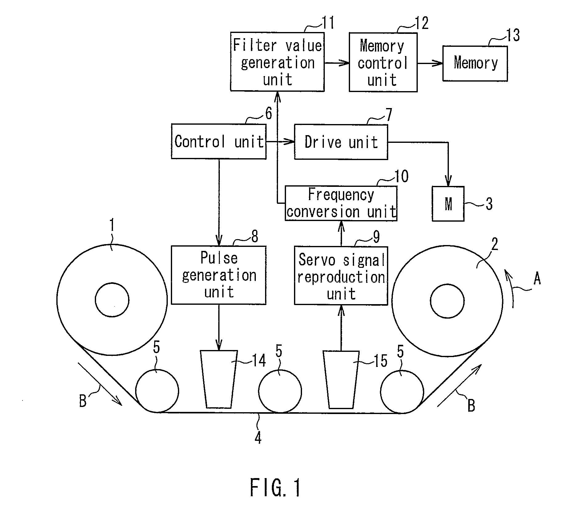
[0028]FIG. 1 is a block diagram of a servo signal recording apparatus according to Embodiment 1. The servo signal recording apparatus of Embodiment 1 is an apparatus for recording a servo signal to a pancake-like magnetic tape 4 wound on a reel 1 in the process of manufacturing magnetic tapes. In some cases, such an apparatus is called a servo writer.

[0029]As illustrated in FIG. 1, the servo signal recording apparatus includes a winding reel 2, a motor 3, guide rollers 5, a controller 6, a drive unit 7, a pulse generation unit 8, a servo signal reproduction unit 9, a frequency conversion unit 10, a filter value generation unit 11, a memory control unit 12, a first servo head 14, and a second servo head 15.

[0030]The winding reel 2 is rotatably driven by the motor 3 in a direction shown by the arrow A and is capable of winding up the magnetic tape 4 that is unwound from the reel 1 mounted on the apparatus of the present invention.

[0031]The motor 3 is drive-controlled by the drive unit...

embodiment 2

[0059]FIG. 6 is a block diagram of a recording and reproduction apparatus according to Embodiment 2. As illustrated in FIG. 6, a recording and reproduction apparatus 20 includes an input terminal 21, a recording signal processing unit 22, an output terminal 23, a reproduction signal processing unit 24, a head unit 25, a control unit 27, an actuator 28, and a memory control unit 29. The recording and reproduction apparatus 20 is capable of attaching and detaching a magnetic tape cartridge 33. The magnetic tape cartridge 33 is provided with a cartridge 30, a magnetic tape 31, and a memory 32. The magnetic tape 31 is wound on a reel mounted within the cartridge 30. The memory 32 is, for example, a semiconductor memory capable of writing and reading information. The memory 32 is incorporated in the cartridge 30. Note that the recording and reproduction apparatus 20 is also provided with a mechanism for running the magnetic tape 31, a control circuit, and the like, which are neither show...


PUM


Abstract

In the apparatus and method of the invention, a servo signal reproduction unit generates a PES from a servo signal reproduced from a magnetic tape, and a frequency conversion unit performs FFT processing of the PES to generate frequency component information. Then, a filter value generation unit generates filter values based on the frequency component information and writes these to a memory. When recording various data signals to the magnetic tape, the filter values are read from the memory and a control filter serving as a notch filter is incorporated into a feedback control for a tracking servo. This enables periodic and narrow-band noise to be removed from a PES, consequently reducing PESs. Accordingly, learning-type optimum notch filter control that allows a magnetic head to follow recording tracks at high speed and with high precision is possible even when the recording track width is reduced and the tape speed is increased.

Description

BACKGROUND OF THE INVENTION[0001]1. Field of the Invention[0002]The present invention relates to a servo signal recording apparatus capable of recording a servo signal to a magnetic tape, and more specifically relates to an information recording apparatus capable of recording a variety of information to a magnetic tape while performing tracking servo control based on the servo signal recorded on the magnetic tape. In particular, the present invention relates to a learning-type optimum notch filter control system adaptable to a data storage system for a computer, and also relates to a recording and reproduction apparatus capable of implementing such a learning-type optimum notch filter control system.[0003]2. Description of Related Art[0004]Magnetic tape has a variety of applications such as audio tape, video tape, and computer tape. Particularly in the field of data backup tapes, magnetic tapes with a recording capacity of 800 GB (giga byte) or more per reel have been commercialized...

Claims


Application Information

Patent Timeline
IPC IPC(8): G11B5/584
CPCG11B5/584
Inventor FUJITA, MASAOKAWAKAMI, SHINJIKAWAKITA, TOSHIOKUSE, SADAMU
Owner FUJIFILM CORP
Why Eureka
Try Eureka