
Hearing aid system with a low power wireless link between a hearing instrument and a telephone

a low-power wireless link and telephone technology, applied in the field of hearing aid systems, can solve the problems of requiring additional power-consuming communications interfaces, prone to interference, and practically impossible to integrate the respective wireless interfaces into hearing instruments directly, so as to avoid or minimize buffering, avoid or minimize transmission protocol overhead, and avoid or minimize coding complexity

Active Publication Date: 2009-12-03
OTICON
View PDF8 Cites 41 Cited by
  • Summary
  • Abstract
  • Description
  • Claims
  • Application Information

AI Technical Summary

Benefits of technology

[0011]An object of the present invention is to provide a relatively simple, reliable scheme for receiving a telephone call in a hearing instrument.
[0045]In a preferred embodiment, the method further comprises using a microphone of the local telephone apparatus for picking up a sound signal from the user and forwarding the sound signal from the user to the remote telephone apparatus. In this way, a good quality, two way telephone connection can be established, which enables a unidirectional link between the telephone apparatus and the hearing instrument, thereby saving power in the hearing instrument.

Problems solved by technology

The problem of the prior art is that the solutions are either relatively complex requiring additional power consuming communications interfaces (e.g. Bluetooth) or prone to interference (receiver to telecoil communication).
The high power consumption of prior art solutions with acceptable audio performance makes it practically impossible to integrate the respective wireless interfaces into hearing instruments directly.

Method used


Image

  • Hearing aid system with a low power wireless link between a hearing instrument and a telephone
  • Hearing aid system with a low power wireless link between a hearing instrument and a telephone
  • Hearing aid system with a low power wireless link between a hearing instrument and a telephone

Examples


Embodiment Construction

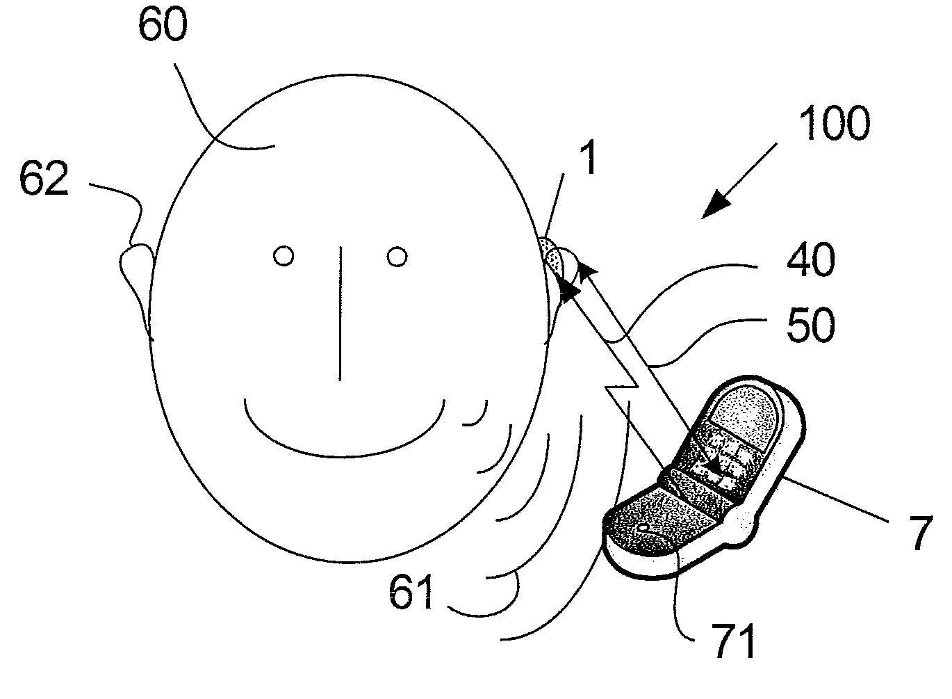
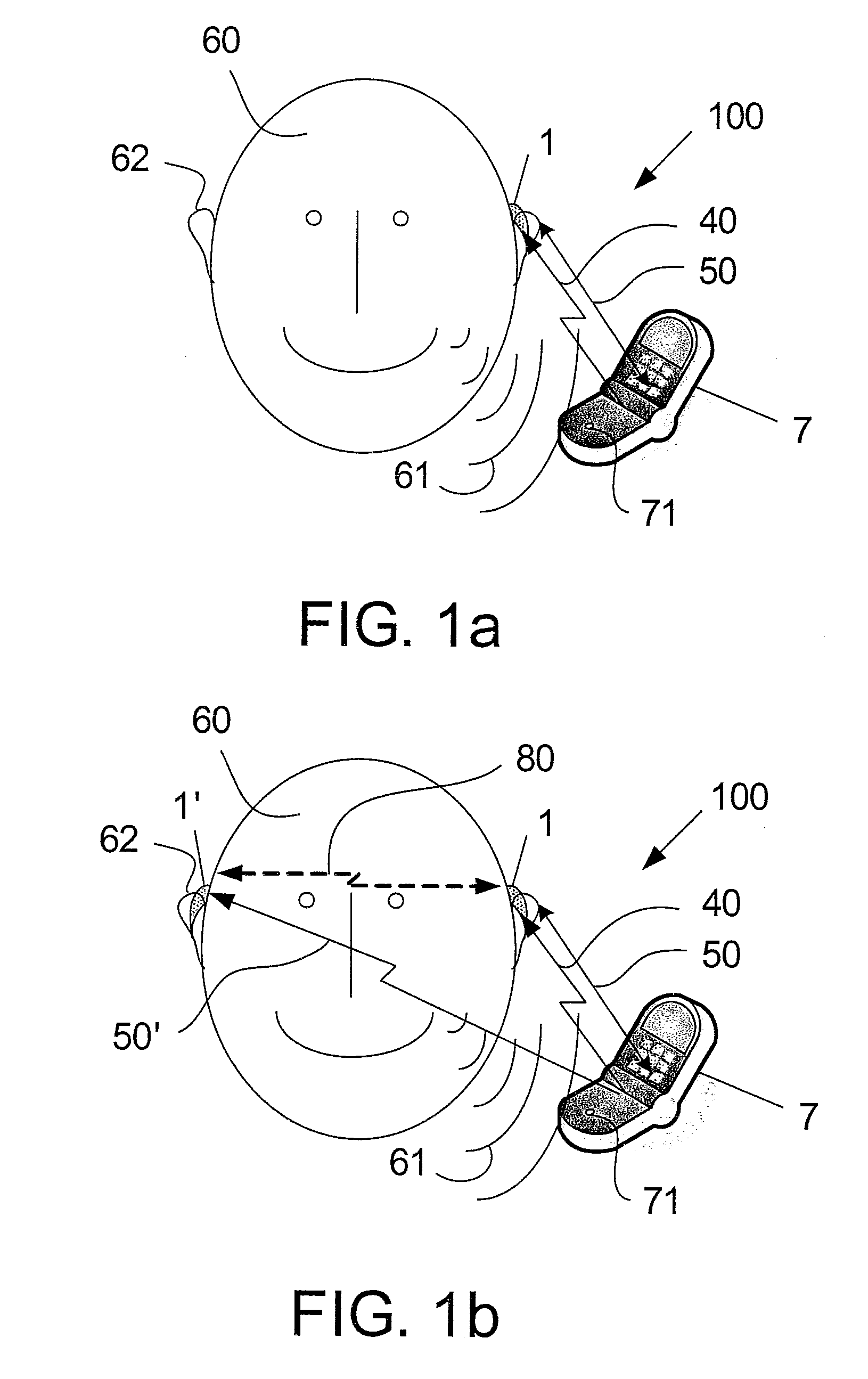
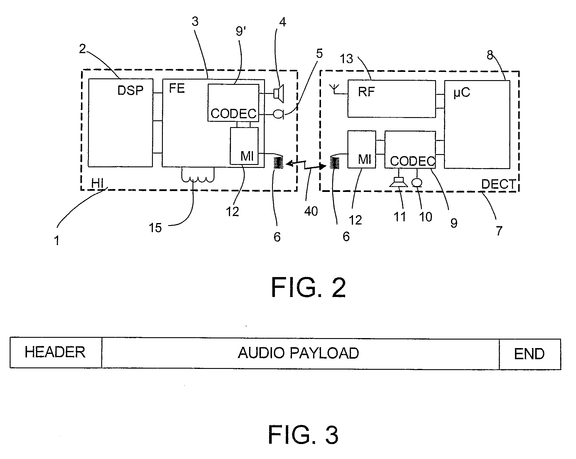
[0055]FIG. 1 shows a hearing aid system 100 according to an embodiment of the invention. The system comprises a digital cordless telephone 7, e.g. a DECT telephone, and a hearing instrument 1, the telephone 7 comprising a transmitter for establishing a digital, short range, low power wireless communications link 40 to a receiver of the hearing instrument 1. The hearing instrument is worn by a user 60 in or (as here) behind an ear 62. The short range wireless link 40 can be established to support a telephone connection from the telephone 7 held by the user 60 in an appropriate (short range, e.g. ≦0.5 m or ≦0.2 m) distance 50 from the hearing instrument 1 to a remote apparatus, e.g. via a public telephone network. During the telephone conversation between the user 60 wearing the hearing instrument, any sounds 61 from the user is picked up by a microphone 71 of the telephone and treated in the normal way by the telephone (i.e. forwarded to a remote apparatus currently connected to the ...


PUM


Abstract

The invention relates to wireless communication between listening devices, in particular to a hearing aid system comprising a hearing instrument and a telephone apparatus. The invention further relates to a method of receiving a telephone call and to the use of a hearing aid system. The object of the present invention is to provide a relatively simple, reliable scheme for receiving a telephone call in a hearing instrument. The problem is solved in that the telephone apparatus comprises a transmitter for establishing a short range digital, low-power link to a hearing instrument comprising a corresponding receiver. This has the advantage of providing a relatively simple and low power solution, where at least the incoming part of a telephone conversation is wirelessly transmitted via a low-power link. The invention may e.g. be used for the communication between a hearing instrument and a telephone, where a standard wireless interface for local connectivity, such as a Bluetooth interface, is not technically feasible or not available for other reasons.

Description

TECHNICAL FIELD[0001]The invention relates to wireless communication between listening devices. The invention relates specifically to a hearing aid system comprising a hearing instrument and a telephone apparatus.[0002]The invention furthermore relates to a method of receiving a telephone call in a hearing instrument adapted for being worn in or at an ear of a user from a remote telephone apparatus via a local telephone apparatus adapted for being held by the user.[0003]The invention furthermore relates to use of a hearing aid system.[0004]The invention may e.g. be useful in applications such as communication between a hearing instrument and a telephone, where a standard wireless interface for local connectivity, such as a Bluetooth interface, is not technically feasible or not available for other reasons.BACKGROUND ART[0005]Number two priority for hearing impaired people is to improve the listening situation when talking into a phone (number one priority being to improve direct voi...

Claims


Application Information

Patent Timeline
Patent Type & Authority Applications(United States)
IPC IPC(8): H04R25/00H04B7/00
CPCH04R25/554H04M1/72591H04M1/72478Y02D30/70
Inventor MULLENBORN, MATTHIASJOHANSEN, MORLEN KJAER
Owner OTICON
Learn More