Connector

a technology of connecting rods and retainers, applied in the direction of electrical equipment, coupling device connections, securing/insulating coupling contact members, etc., can solve the problem of insufficient detection of retainer insertion reliably, and achieve the effect of suppressing reducing the influence of resin flow

Active Publication Date: 2009-12-03
SUMITOMO WIRING SYST LTD
View PDF11 Cites 5 Cited by
  • Summary
  • Abstract
  • Description
  • Claims
  • Application Information

AI Technical Summary

Benefits of technology

[0011]The reinforcements strengthen parts of the retainer that contact the receptacle when the retainer is inserted insufficiently. These reinforced parts are not likely to be damaged by contact with a mating connector. Therefore the insufficient insertion of the retainer can be detected reliably. Additionally, the reinforcements are at the rear ends of the side walls in the inserting direction of the retainer and project in from the front end portions of the side wall portions. Thus, it is not necessary to increase the thickness of the entire side walls and widen the connector in the arrangement direction of the cavities. Further, the housing wall is thinned to form recesses for the reinforcements only at the opposite ends of the housing. Thus, influence on the flow of resin can be suppressed to a minimum level and the housing walls need not be thickened. Accordingly, the insufficient insertion of the retainer is detected reliably without enlarging the connector.
[0012]Large and small terminals may be accommodated in the housing. The small terminals preferably are in a middle part of the housing in the arrangement direction of the cavities and the large terminals are at opposite sides of the housing. Accordingly, the thickness of the housing wall at the opposite widthwise sides inevitably increases as compared with the case where the small terminals are at the opposite sides. Thus, the recesses for the reinforcements are in the parts of the housing where the wall thickness inevitably is large to reduce the influence on the flow of resin even more.

Problems solved by technology

Therefore the insufficient insertion of the retainer can be detected reliably.

Method used


Image

  • Connector
  • Connector
  • Connector

Examples


Embodiment Construction

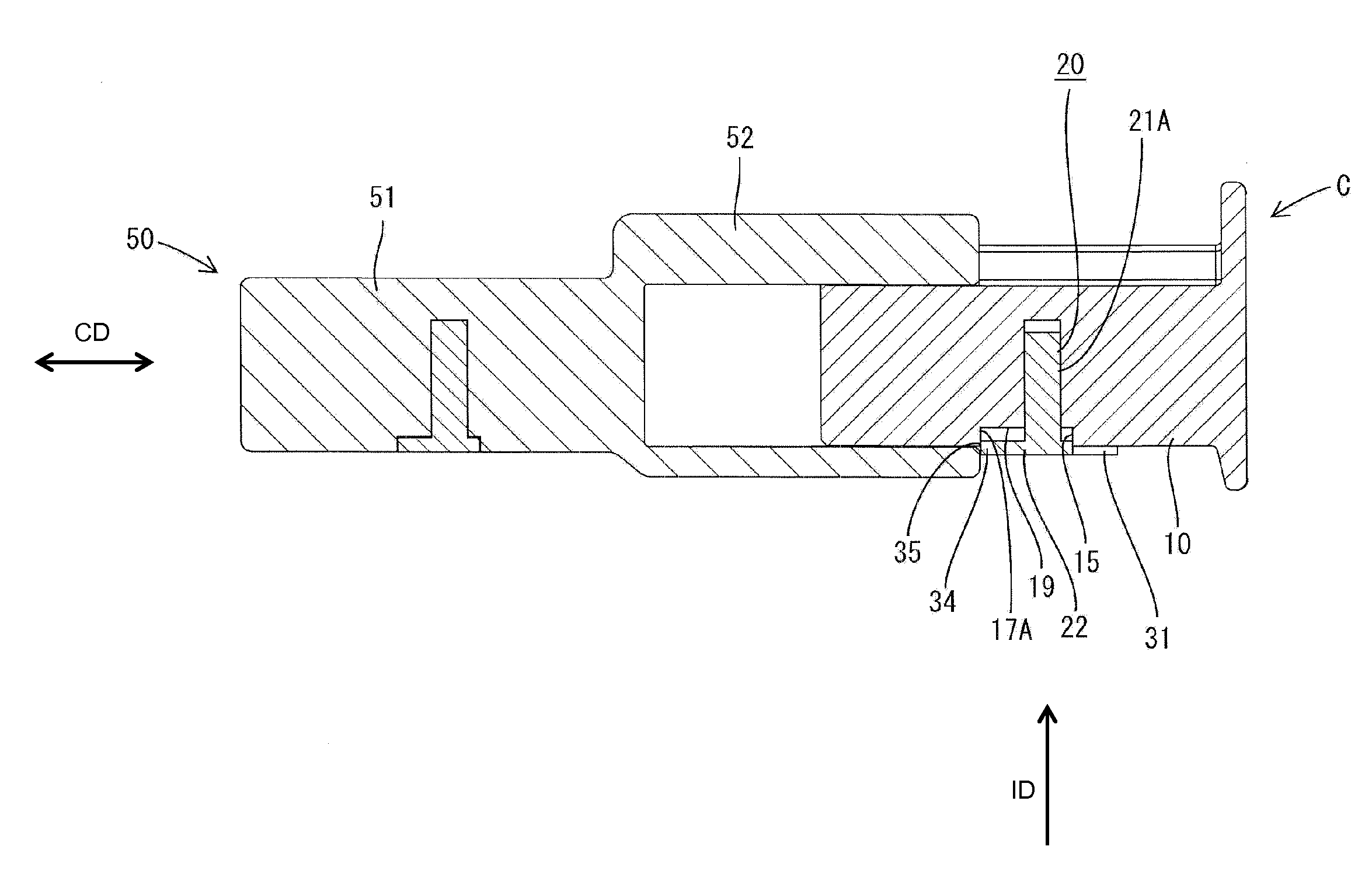
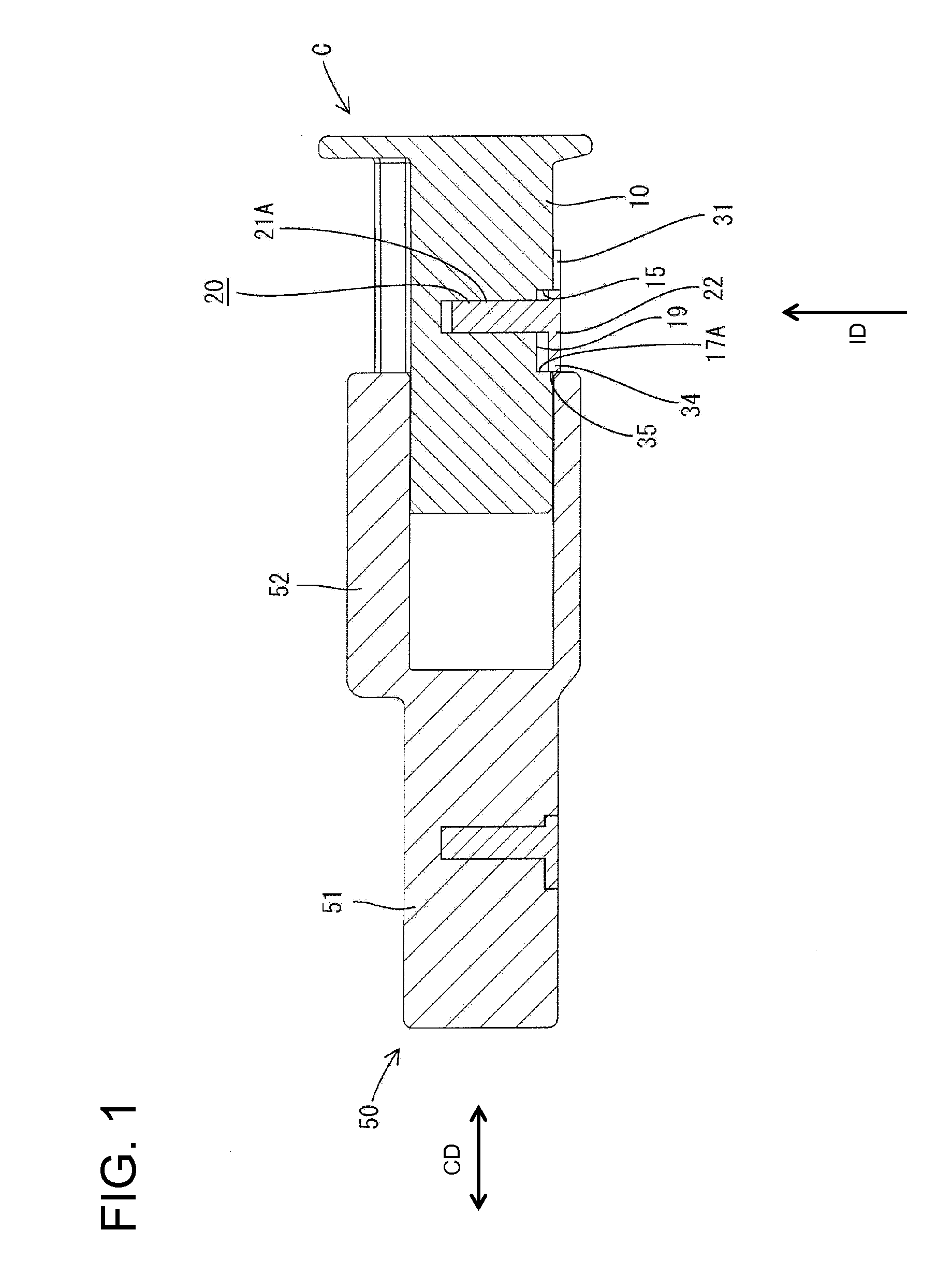
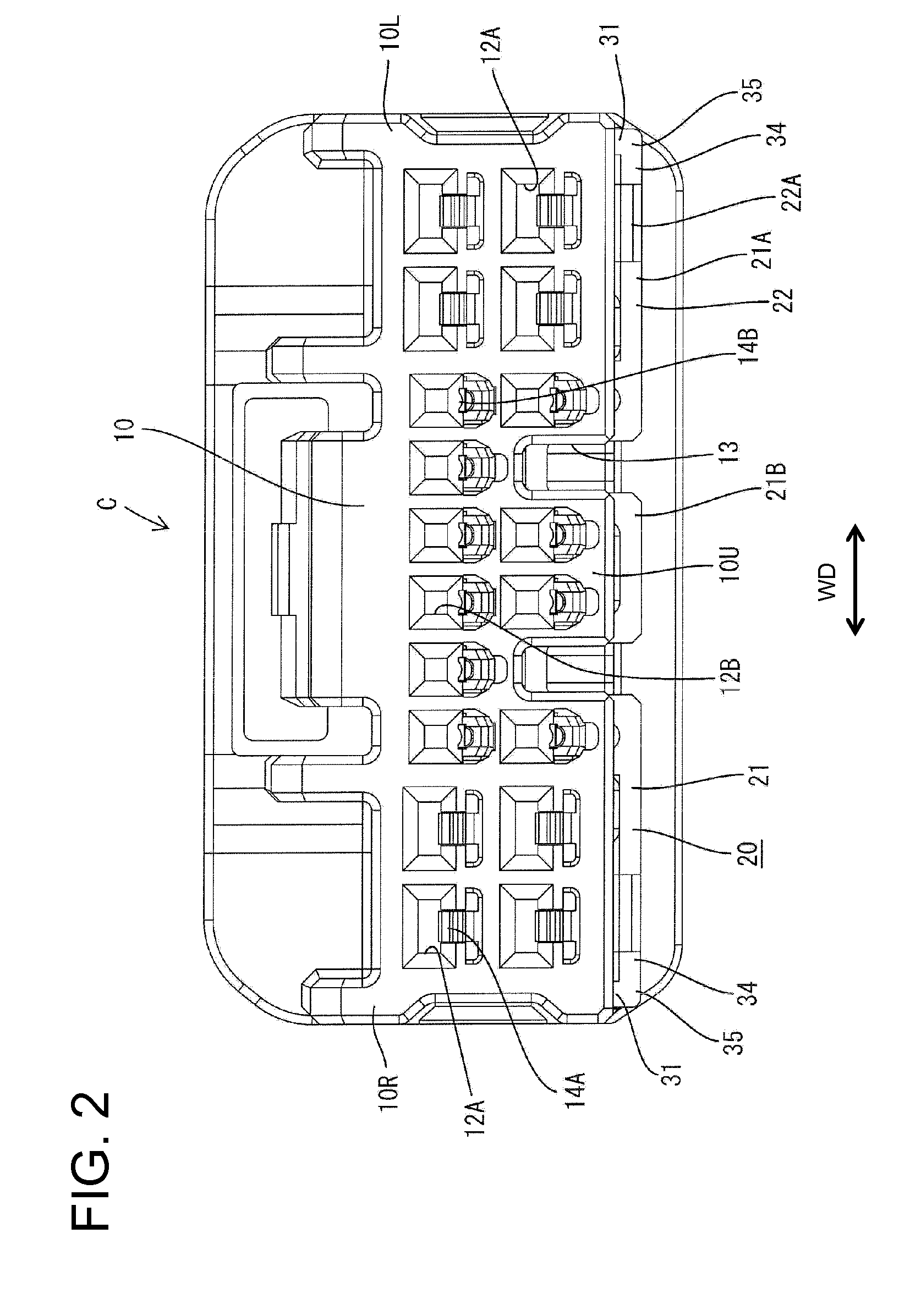
[0027]A connector in accordance with the invention is identified by the letter C in FIGS. 1, 2 and 7. The connector C is a hybrid type connector that has both large and small terminals and is connectable with a mating connector 50. Ends of the connectors C, 50 that are to be connected are referred to as the front ends. Additionally, the orientation of FIG. 2 provides the basis for reference to the upper, lower, left and right sides.

[0028]The mating connector 50 includes a housing 51 made e.g. of synthetic resin and a forwardly open tubular receptacle 52 is provided in a front part of the housing 51. Tabs of unillustrated mating terminals are held in the housing 51 and project forward in the receptacle 52. Ribs (not shown) project in from the bottom wall of the receptacle 52.

[0029]The connector C includes a synthetic resin housing 10 that can be inserted into the receptacle 52 of the mating connector 50. Large and small terminals (not shown) are accommodated in the housing 10 in conf...


PUM


Abstract

A connector is provided with a housing 10 fittable into a receptacle 52 of a mating connector 50 and a retainer 20 to be inserted into the housing 10 sideways. Cavities 12A, 12B for accommodating terminals are arranged side by side in the housing. The retainer 20 includes a main body 21 with side by side engaging portions 26A, 26B for engaging the terminals. Side walls 31 are provided at the opposite ends in an arrangement direction of the engaging portions 26A, 26B and projecting forward from the main body 21 in a connecting direction with the mating connector 50. Reinforcements 34 project in from front end portions of the side walls 31 in the connecting direction with the mating connector 50 and are at the rear ends of the side walls 31 in an inserting direction of the retainer 20 into the housing 10.

Description

BACKGROUND OF THE INVENTION[0001]1. Field of the Invention[0002]The invention relates to a connector mounted with a side type retainer.[0003]2. Description of the Related Art[0004]Known connectors include housings for receiving terminals and retainers that can be inserted through side surfaces of housings for doubly locking the terminals. A part of the retainer projects from the side surface of the housing if the retainer is inserted insufficiently into the housing. This projecting part of the retainer contacts the receptacle of a mating connector to hinder connection and to detect insufficient insertion of the retainer. Thus, the retainer is reinserted and the terminals are locked redundantly at proper positions.[0005]Side type retainers are made in various shapes. For example, U.S. Pat. No. 6,390,859 discloses a retainer with a main body that has terminal engaging portions arranged side by side. Side walls are formed at the opposite sides of the main body. The side walls on retain...

Claims


Application Information

Patent Timeline
Patent Type & Authority Applications(United States)
IPC IPC(8): H01R13/436H01R13/514
CPCH01R13/4362
Inventor KOJIMA, EIJI
Owner SUMITOMO WIRING SYST LTD
Why Eureka
Try Eureka