Check patentability & draft patents in minutes with Patsnap Eureka AI!

Display device provided with touch panel

a display device and touch panel technology, applied in the field of display devices provided with touch panels, can solve the problems of difficult to realize a high resistance and the deterioration of touch position detection precision, and achieve the effect of improving the detection precision of touch position

Active Publication Date: 2009-12-10
GLOBAL OLED TECH
View PDF7 Cites 53 Cited by
  • Summary
  • Abstract
  • Description
  • Claims
  • Application Information

AI Technical Summary

Benefits of technology

[0044]According to the present invention, it is possible to provide a display device provided with a touch panel having an improved touch position detection precision.

Problems solved by technology

However, if a touch panel with a smooth electrode surface is used, it is difficult to realize a high resistance, and the touch position detection precision deteriorates since the parasitic capacitance increases.

Method used


Image

  • Display device provided with touch panel
  • Display device provided with touch panel
  • Display device provided with touch panel

Examples


embodiment

[0072]A liquid crystal display device will now be described in detail with reference to the drawings, as a display device provided with a touch panel according to an embodiment.

[0073](Configuration of Liquid Crystal Display Device 50 Provided with Touch Panel 10)

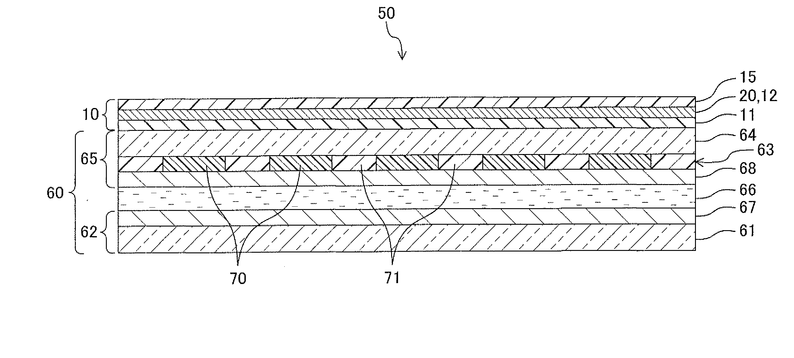
[0074]FIG. 1 is a cross-sectional view of a liquid crystal display device 50 provided with a touch panel 10 according to an embodiment of the present invention.

[0075]The liquid crystal display device 50 includes the touch panel 10, a liquid crystal display panel 60 provided on the reverse surface of the touch panel 10, and a backlight (not shown) provided on the reverse surface of the liquid crystal display panel 60.

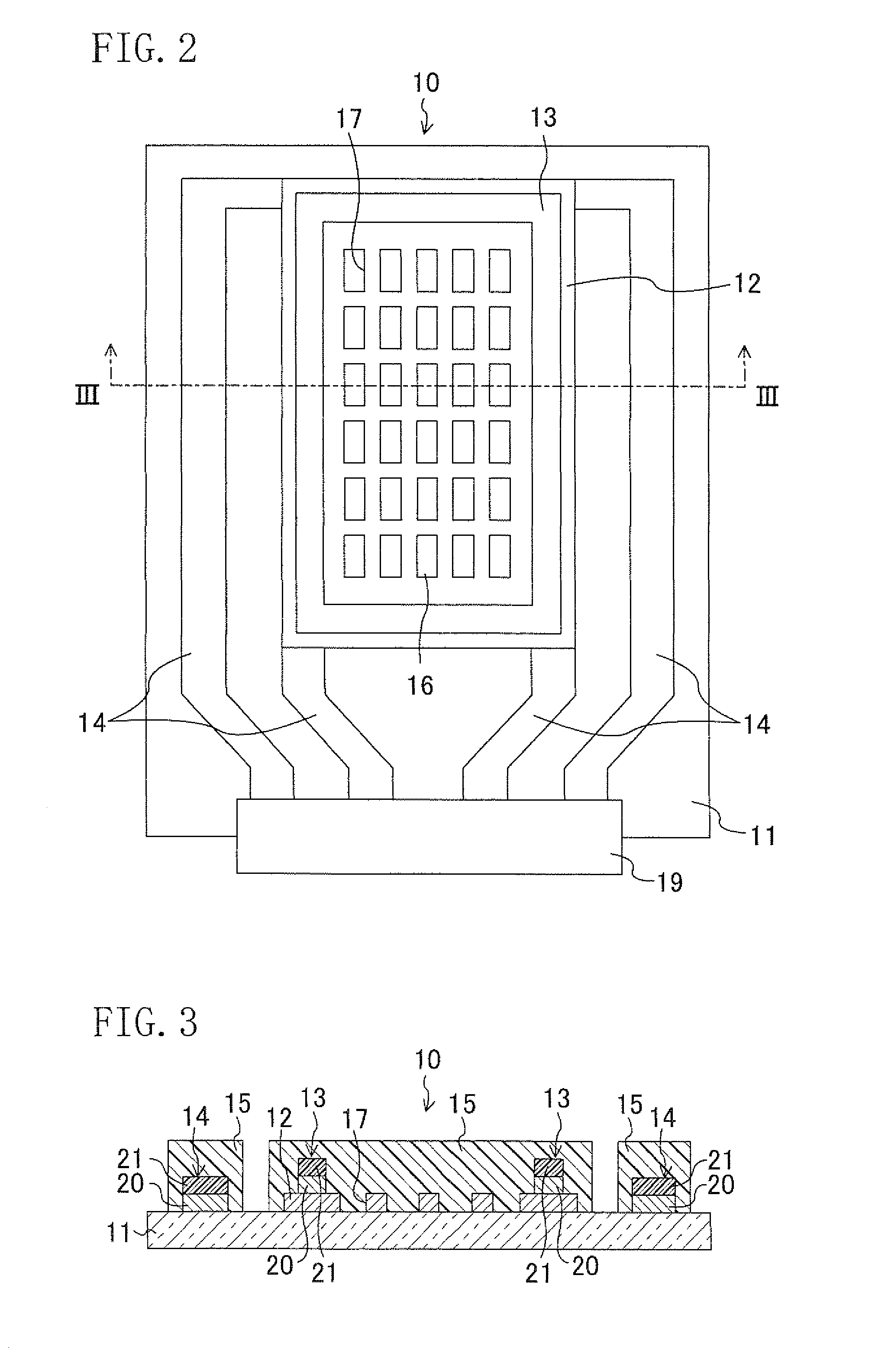
[0076]First, the touch panel 10 will be described. FIG. 2 shows a plan view of the touch panel 10, and FIG. 3 shows a cross-sectional view of the touch panel 10 taken along line III-III of FIG. 2.

[0077]The touch panel 10 includes an insulative substrate 11, an in-panel-surface electrode 12 formed on the insulativ...


PUM


Abstract

A display device provided with a touch panel for detecting a contact position on a touch surface of the panel at which a contact object is brought into contact with the touch surface, the touch panel including an in-panel-surface electrode with a plurality of openings formed in a display area.

Description

TECHNICAL FIELD[0001]The present invention relates to a display device provided with a touch panel.BACKGROUND ART[0002]Touch panels, attached on display elements such as liquid crystal display elements, have been researched and developed, as one of the input means for liquid crystal display devices, etc. A touch panel of this type normally includes a flat-plate electrode formed on an insulative substrate such as a glass substrate for detecting the contact position based on an electric signal that is influenced by changes in capacitance occurring when a contact object is brought into contact with the panel surface.[0003]Since an electrode in a panel surface used in a touch panel as described above is required to have a high resistance and a high transmittance, a thin transparent conductive film such as an ITO film (thickness: about 100 Å) has been mainly used as disclosed in, for example, Patent Document 1, Patent Document 2, etc.[0004]Patent Document 1: Japanese Laid-Open Patent Pub...

Claims


Application Information

Patent Timeline
IPC IPC(8): G06F3/041
CPCG06F3/044G06F3/0443
Inventor YAMATO, ASAHITAKAHASHI, KAZUKINAKATA, JUN
Owner GLOBAL OLED TECH
Features
  • R&D
  • Intellectual Property
  • Life Sciences
  • Materials
  • Tech Scout
  • Unparalleled Data Quality
  • Higher Quality Content
  • 60% Fewer Hallucinations
Learn More