Wireless Power Transmitting Apparatus

a power transmitting apparatus and wireless technology, applied in the direction of parallel/serial switching, electromagnetic wave system, battery arrangement for several simultaneous batteries, etc., can solve the problems of significant inconvenience for users, limited electronic products for inductance coil locations, and the majority of power dissipation in the air

Inactive Publication Date: 2009-12-10
NAT TAIPEI UNIV OF TECH
View PDF35 Cites 63 Cited by
  • Summary
  • Abstract
  • Description
  • Claims
  • Application Information

AI Technical Summary

Problems solved by technology

Therefore, while a user buys a power-consuming electronic product, he or she has to buy charging devices corresponding to the bought power-consuming electronic product for serving as media of transmitting power, and it indicates significant inconveniences for the user.
While the wireless power transmitting technologies are implemented with inductance coils, power are transmitted by low-frequency transformation between magnetic energy and electric power; however, only a significantly small amount of power may reach the inductance coils as receiving power, and it indicates that most of power dissipates in the air while the distance between the inductance coils for power transmission increases.
Besides, since a transmitting frequency of the inductance coils is usually inconsistent with a receiving frequency of an electronic product for receiving power transmitted from said inductance coils, additional inductance coils having a consistent receiving frequency with the transmitting frequency of the inductance coils for transmitting power have to be disposed within the electronic product for power transmissions.
However, the popular electronic products are usually required to possess small weight and compact size, and the inductance coils fail in meeting requirements of a qualified power transmission ratio, locations on the electronic products for the inductance coils are thus limited significantly.
While an emitting antenna having high directivity is used for emitting the abovementioned high-frequency wave beams, the electronic product is able to receive power with a high efficiency; however, it is also getting expensive in designing the receiving circuit of the electronic product, and feasible locations of the electronic product for receiving the emitted power also meet more limitations.
While the disclosed resistive surface is used on a housing of a wireless power transmitting apparatus, power transmitted from the emitting antenna may be effectively restricted within a specific space.
However, the high impedance surface 300 has to be implemented with large amounts of conductive via 322 and 332 so as to bring a larger volume and an expensive fabrication cost of the wireless transmitting apparatus having the housing the high impedance surface 300.

Method used


Image

  • Wireless Power Transmitting Apparatus
  • Wireless Power Transmitting Apparatus
  • Wireless Power Transmitting Apparatus

Examples


Embodiment Construction

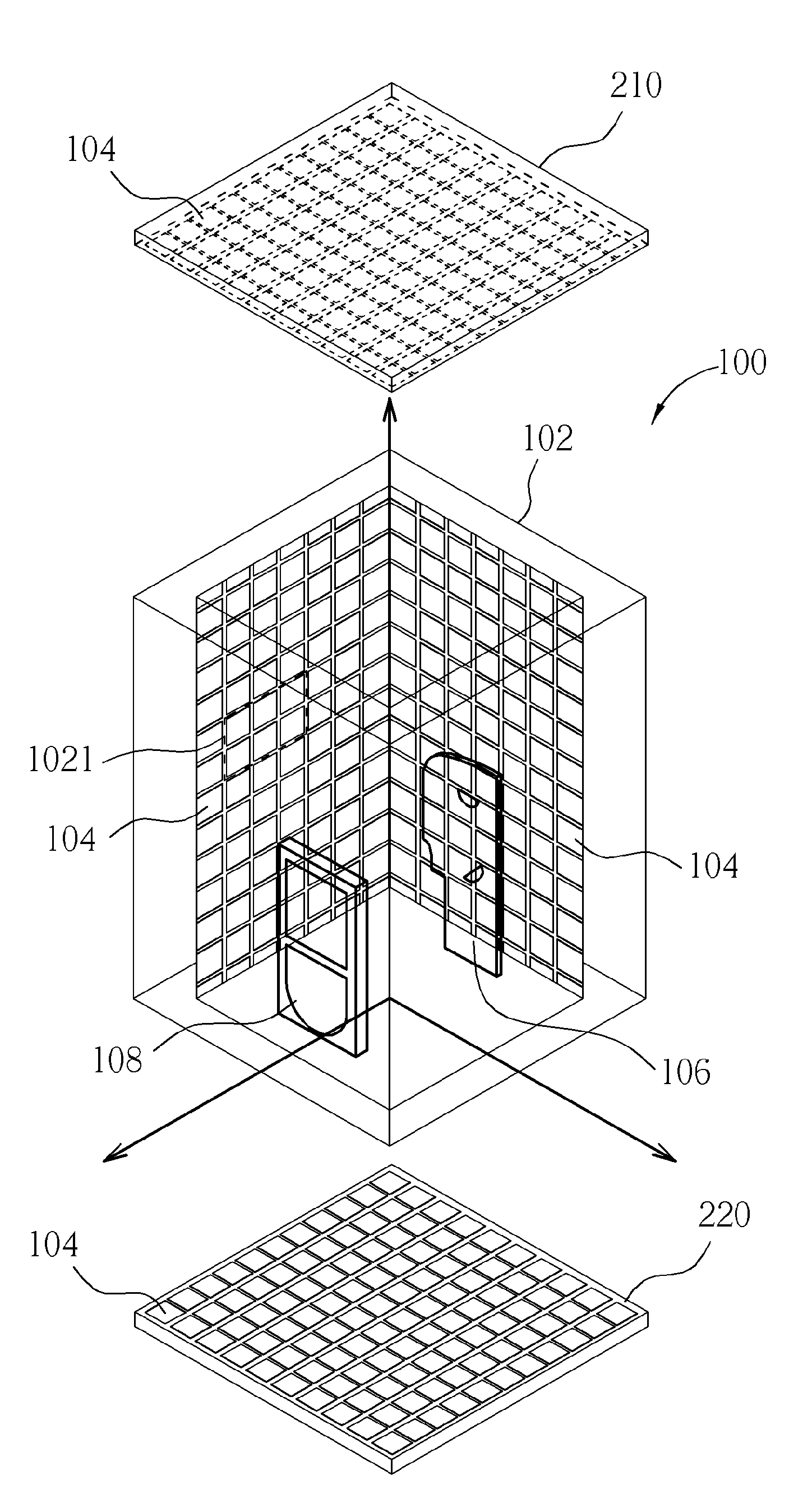
[0021]To overcome significant power dissipation of the wireless power transmission in the prior art, and to relieve the expensive fabrication cost, the large volume, and technical bottlenecks of the wireless power transmitting apparatus, the present invention discloses a wireless power transmitting apparatus for delivering power from a power transmitting device to a power receiving device. The wireless power transmitting apparatus of the present invention is primarily implemented with a sealed metal housing having an irregular and unspecific geometric shape, and with specific polygon-shaped conductive slices disposed on inner surfaces of the sealed metal housing so that high impedance against electromagnetic waves is generated on the inner surfaces of the sealed metal housing. With the generated high impedance, dissipation of electromagnetic waves is efficiently prevented so that a power receiving device disposed at an arbitrary location inside the sealed metal housing is capable of...


PUM


Abstract

A wireless power transmitting apparatus for remotely transmitting energy is implemented with a closed metal housing and a plurality of conductive plates disposed within the closed metal housing. With the aid of a high impedance between the closed metal housing and the conductive plates, a surface having the high impedance is formed on both the closed metal housing and the conductive plates for constraining electromagnetic power within the closed metal housing from dissipating and being consumed. The wireless power transmitting apparatus is not merely able to effectively and uniformly restrict electromagnetic field energy to the closed metal housing with the aid of the high impedance, but is also be able to raise a power transmitting efficiency between a power emitting device and a power receiving device.

Description

BACKGROUND OF THE INVENTION[0001]1. Field of the Invention[0002]The present invention relates to a wireless power transmitting apparatus, and more particularly, to a wireless power transmitting apparatus for transmitting power from a power emitting device to a power receiving device.[0003]2. Description of the Prior Art[0004]For electronic products charged by combining devices including conventional wires and transformers, power of the electronic products may merely be transmitted by using specific apparatuses fitting specifications of the electronic products. Therefore, while a user buys a power-consuming electronic product, he or she has to buy charging devices corresponding to the bought power-consuming electronic product for serving as media of transmitting power, and it indicates significant inconveniences for the user. For accommodating such a user in charging the bought electronic product, some wireless power transmitting technologies come out.[0005]Primary existing wireless ...

Claims


Application Information

Patent Timeline
Patent Type & Authority Applications(United States)
IPC IPC(8): H05K9/00
CPCH02J17/00H02J7/0027H02J50/12H02J50/70H02J50/005H02J50/20H02J7/0044H02J2310/22H02J7/0024
Inventor MAO, SHAU-GANG
Owner NAT TAIPEI UNIV OF TECH
Why Eureka
Try Eureka