Cleaner head assembly for a vacuum cleaner

a vacuum cleaner and cleaning head technology, which is applied in the direction of suction cleaners, cleaning equipment, suction nozzles, etc., can solve the problems of not maintaining good contact between the cleaning head and the surface to be cleaned, the cleaning head cannot maintain good contact in both directions, and the cleaning head cannot move away from the optimal, so as to improve the ability of the cleaning head to pick up debris and improve the sealing of the suction opening

Inactive Publication Date: 2009-12-17
DYSON TECH LTD
View PDF6 Cites 4 Cited by
  • Summary
  • Abstract
  • Description
  • Claims
  • Application Information

AI Technical Summary

Benefits of technology

[0015]Preferably a flicker strip is provided to improve sealing of the suction opening with the surface to be cleaned and more preferably, a support strip or carpet strips are provided to improve the ability of the cleaner head assembly to pick up debris from carpet.

Problems solved by technology

In most cases the cleaner head will be acted upon in different ways by the carpet when it is travelling in different directions and will not maintain good contact on all sides of the dirty air inlet in both directions.
Furthermore, the action of the user can result in the angle of inclination of the handle to the vertical being varied quite significantly during normal use and this can cause the plane of the dirty air inlet to be lifted, either at the front or the back, away from the optimum configuration.
The weight and the mounting arrangement of a separate brush bar motor on the cleaner head may also contribute to the cleaner head not maintaining good contact with the surface to be cleaned and moving away from the optimum configuration of the dirty air inlet.
Any and all of these things can result in a reduction in the effectiveness of the suction of the cleaner head which can lead to a loss in the maximum level of pick-up and then to customer dissatisfaction.
However, these mechanisms only lift and lower the cleaner head by pivoting about the axis about which the cleaner head is connected to the main body of the cleaner.
They do not address the problem of the dirty air inlet becoming inclined to the optimum configuration and thereby allowing the inlet suction to become less effective.
The difficulty associated with this arrangement is that the cradle must be sealed with respect to the cleaner head and this can be difficult to achieve.
However, the constant movement and, in some cases, the weight of a motor on the brush bar can cause the brush housing to be lifted away from the floor surface.
This is undesirable as the inlet suction becomes less effective.

Method used


Image

  • Cleaner head assembly for a vacuum cleaner
  • Cleaner head assembly for a vacuum cleaner
  • Cleaner head assembly for a vacuum cleaner

Examples


Embodiment Construction

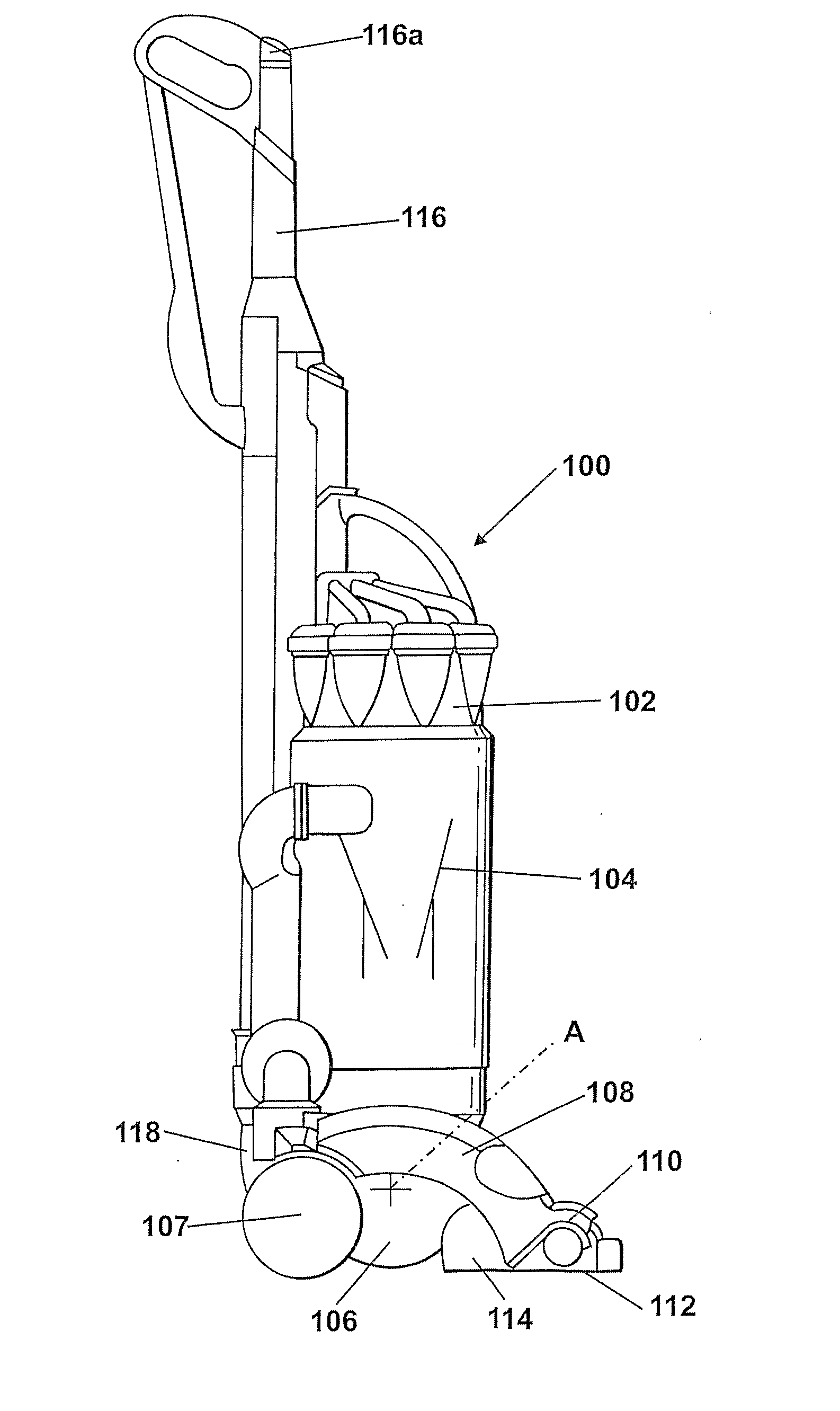
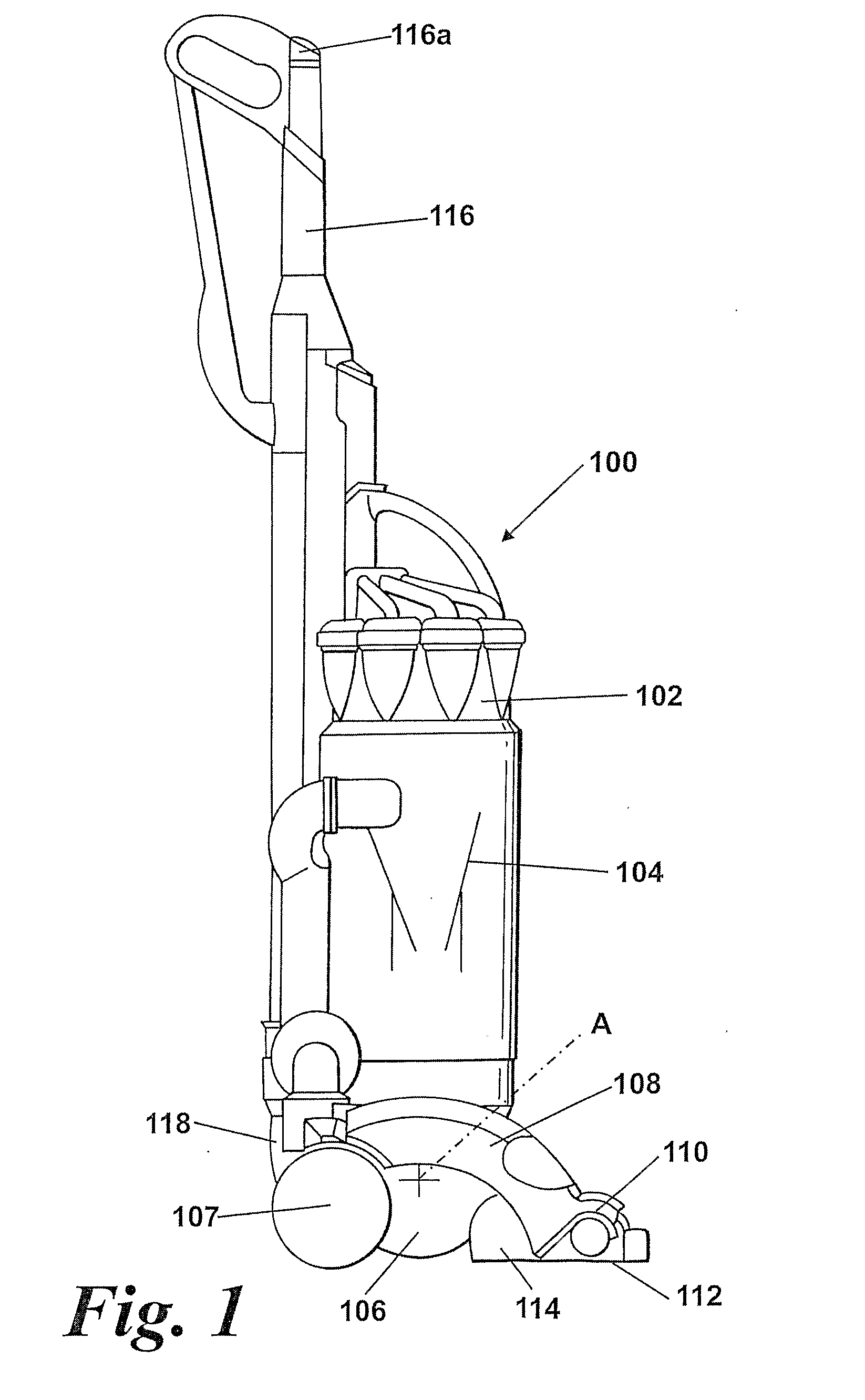
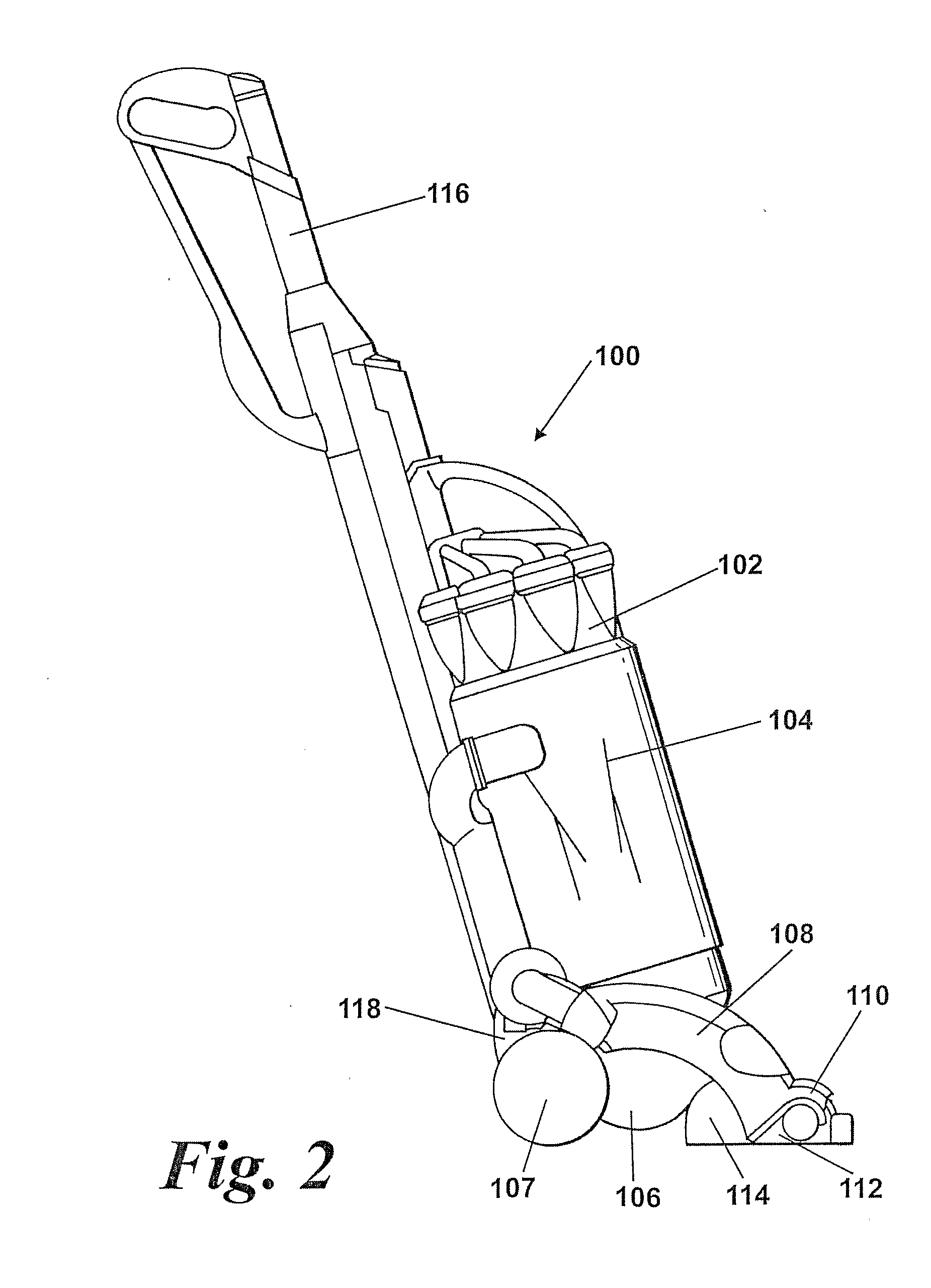
[0025]FIGS. 1 and 2 illustrate the overall construction of an upright vacuum cleaner incorporating a cleaner head assembly according to the invention. The vacuum cleaner 100 has a main body 102 in which dust separation apparatus 104 is housed. In FIGS. 1 and 2 the dust separation apparatus 104 is shown schematically. The embodiment may comprise cyclonic dust separation apparatus consisting of two cyclones arranged in series. Apparatus of this type is well known and will not be described any further here because it has no material effect on the invention. A motor housing 106 is located at the lower end of the main body 102 and forms part of the main body 102. Supporting wheels 107 are mounted directly on the side of the motor housing 106. A cleaner head assembly 108 is rotatably mounted on the motor housing 106 about an axis A. The cleaner head assembly 108 has a brush housing 110 with a downward facing inlet 112 arranged at the forward end of the cleaner head assembly 108. A brush b...


PUM


Abstract

A cleaner head assembly for a vacuum cleaner includes a cleaner head body pivotably attachable to a main body of a vacuum cleaner and a brush housing pivotably mounted on the cleaner head body, the brush housing having a suction opening, a brush bar mounted therein and a resilient member provided to bias the brush housing in a pivoting direction so as to urge a rear portion of the brush housing in an upward direction with respect to the cleaner head body. This configuration allows the brush housing to be doubly articulated with respect to the main body of the vacuum cleaner as it is biased by the resilient member in the pivoting direction such that the rear portion of the brush housing is urged in an upward direction with respect to the cleaner head body and the suction opening remains in a horizontal plane.

Description

REFERENCE TO RELATED APPLICATIONS[0001]This application is a national stage application under 35 USC 371 of International Application No. PCT / GB2007 / 002701, filed Jul. 16, 2007, which claims the priority of United Kingdom Application No. 0615683.0, filed Aug. 8, 2006, the contents of which prior applications are incorporated herein by reference.FIELD OF THE INVENTION[0002]The present invention relates to a cleaner head assembly for a vacuum cleaner.BACKGROUND OF THE INVENTION[0003]An upright vacuum cleaner normally comprises a main body containing dirt and dust separating apparatus, a cleaner head rotatably mounted on the main body and having a dirty air inlet, and a motor and fan unit for drawing dirty air into the dirt and dust separating apparatus via the dirty air inlet so that dirt and dust can be separated from the airflow before the clean air is expelled to the atmosphere. The dirty-air inlet or suction opening through which dirty air is sucked into the vacuum cleaner is dire...

Claims


Application Information

Patent Timeline
Patent Type & Authority Applications(United States)
IPC IPC(8): A47L5/34
CPCA47L9/04A47L5/30
Inventor BERNARD, SAMUEL DAVIDTOWNSEND, MARTIN DAVID
Owner DYSON TECH LTD
Why Eureka
Try Eureka