Hydraulic motor for railway switches

Active Publication Date: 2009-12-17
GENERAL ELECTRIC CO
View PDF1 Cites 3 Cited by
  • Summary
  • Abstract
  • Description
  • Claims
  • Application Information

AI Technical Summary

Benefits of technology

[0006]The present invention is directed to an apparatus that is used to control and drive the moving of the rail end points of switch point assemblies. Towards this end, a control mechanism for a railroad switch machine is disclosed. The mechanism has a hydraulic circuit. The hydraulic circuit is operable to move a rail end point of a switch point assembly of the railroad switch machine. A pump to hydraulically operate the hydraulic circuit, and a motor to operate the pump are also pro

Problems solved by technology

The device described in that patent operates switch points which are independent, or disconnected, from each other, and it is not applicab

Method used


Image

  • Hydraulic motor for railway switches
  • Hydraulic motor for railway switches
  • Hydraulic motor for railway switches

Examples


Embodiment Construction

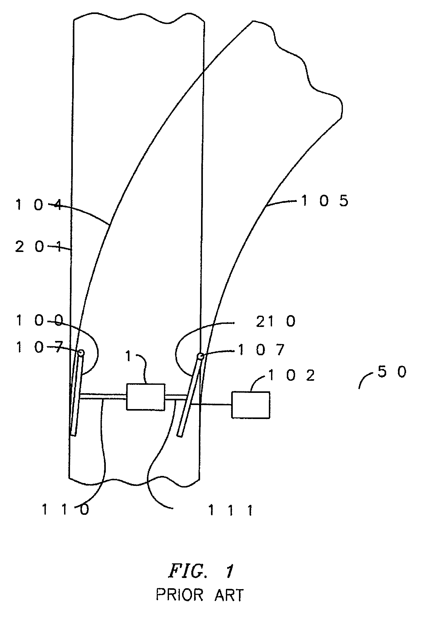
[0012]With reference to the figures, exemplary embodiments of the invention will now be described. The present invention is disclosed below specific to a pivoting connector. The scope of the present invention is not limited to a pivoting connector within a switch machine. Specifically, the present invention may be implemented in association with other moving parts of a switch machine.

[0013]Present systems used to control and drive the moving of the rail end points of switch point assemblies are mainly electromechanical. These systems employ components, such as high current relays, contactors, pressure switches and others, which are particularly sensitive to environmental or ambient, conditions, such as but not limited to temperature, humidity and mechanical stress, which can be extreme in railway applications. Railway applications would greatly benefit from control systems and actuators that can offer a higher mean time between failure (MTBF) and can be implemented with devices and ...


PUM


Abstract

A control mechanism for a railroad switch machine, the mechanism including a hydraulic circuit operable to move a rail end point of a switch point assembly of the railroad switch machine, a pump to hydraulically operate the hydraulic circuit, and a motor to operate the pump, wherein the only electromechanical parts of the control mechanism are within the motor.

Description

FIELD OF THE INVENTION[0001]The present invention relates to railway switching machines and, in particular, to an apparatus which is used to control and drive the moving of the rail end points of switch point assemblies.BACKGROUND OF THE INVENTION[0002]As is commonly known, railway switch point assemblies include two rail end points which are tapered rail profiles capable of deflecting to move between two different positions in order to facilitate the correct alignment of the track components for the desired path of rolling stock transiting through the switch point assembly. The switch point assembly has two deflectable or movable rail end points which move in concert with one another between first and second alternative positions. In a first alternative position, a first one of these movable rail end points can be aligned with a first fixed stock rail to facilitate passage of the rolling stock straight through the switch point onto a first set of fixed rails. In a second alternativ...

Claims


Application Information

Patent Timeline
IPC IPC(8): B61L5/04
CPCB61L5/045
Inventor BIAGIOTTI, MAURIZIO
Owner GENERAL ELECTRIC CO
Why Eureka
Try Eureka