
Methods and Systems for RFID Reader Power Management

Inactive Publication Date: 2009-12-17
SYMBOL TECH INC
View PDF3 Cites 72 Cited by
  • Summary
  • Abstract
  • Description
  • Claims
  • Application Information

AI Technical Summary

Problems solved by technology

This leads to a higher power consumption by the RFID reader which is detrimental in attaining sustainable operation time, such as for an 8 hour shift.
In such applications, using a conventional constant power continuously operating RFID reader does not optimize power consumption by the RFID reader.
This results in a faster discharge of RFID reader batteries and subsequent frequent interruptions in normal operation of the RFID reader.
Further, without a capability to vary output power levels of an RFID reader antenna, the RFID reader can incur misses in reading some RFID tagged objects that move out of range, if the RFID reader is not at its maximum output power level.
Conventional RFID readers lack any form of power variation, or optimization of power consumption.
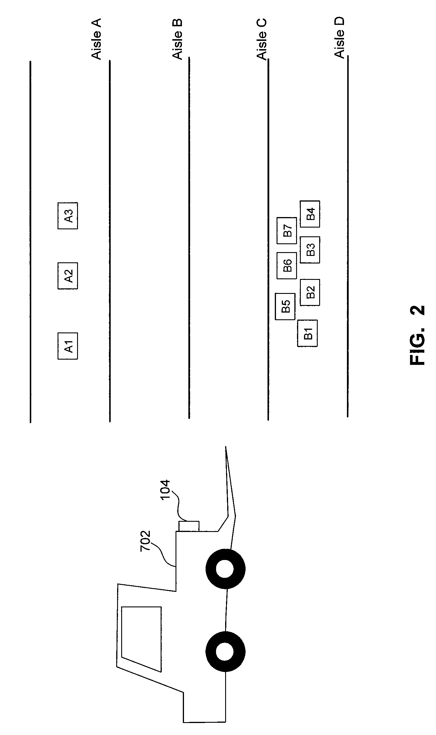
Continually reading a tag while the same box is on a forklift is an inefficient use of reader battery power.
Both the current solutions are wasteful in terms of power consumption.
For example, in an RFID reader controlled by a timer, power may still be consumed if the forklift has completed inventory operations and come to a rest before the timer has reset.
Therefore a lack of any form of motion detection to determine whether or not a forklift is operating in an inventory read operation leads to a waste in valuable battery capacity of the RFID reader and necessitates frequent recharge operations thereby disrupting normal inventory operations.
In scenarios where RFID tags are moving (e.g., on a conveyor belt), conventional RFID readers are left continuously ON between detection of two successive tags, also leading to a waste of RFID reader battery and power resources.

Method used


Image

  • Methods and Systems for RFID Reader Power Management
  • Methods and Systems for RFID Reader Power Management
  • Methods and Systems for RFID Reader Power Management

Examples


Embodiment Construction

1.0 Introduction

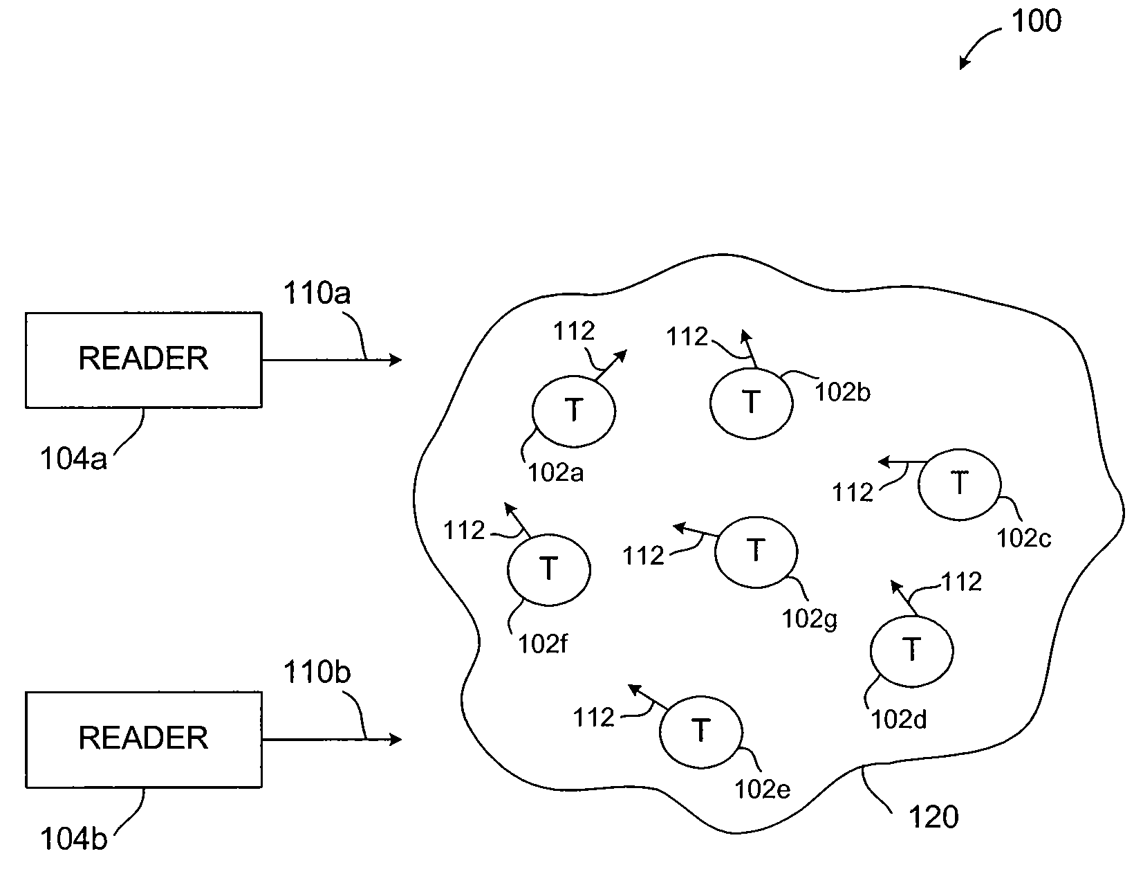
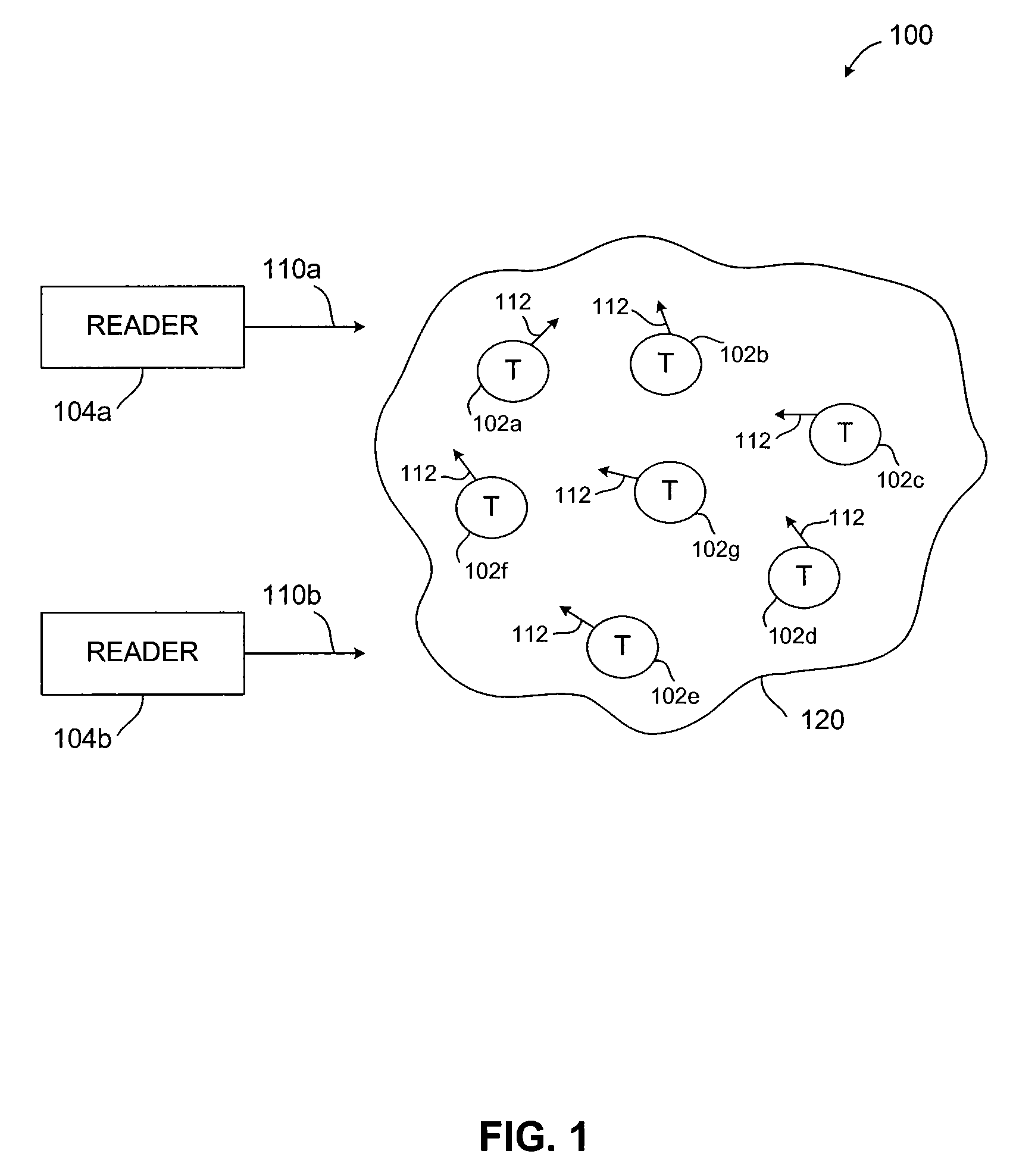
[0020]Methods, systems, and apparatuses for RFID devices are described herein. In particular, methods, systems, and apparatuses for managing power levels of an RFID reader without manual intervention are described. Such methods systems, and apparatuses also increase battery life and time between recharging an RFID reader.

[0021]The present specification discloses one or more embodiments that incorporate the features of the invention. The disclosed embodiment(s) merely exemplify the invention. The scope of the invention is not limited to the disclosed embodiment(s). The invention is defined by the claims appended hereto.

[0022]References in the specification to “one embodiment,”“an embodiment,”“an example embodiment,” etc., indicate that the embodiment described may include a particular feature, structure, or characteristic, but every embodiment may not necessarily include the particular feature, structure, or characteristic. Moreover, such phrases are not necessarily r...


PUM


Abstract

Methods, systems, and apparatuses for managing power consumed by an RFID reader are described. Such methods, systems and apparatuses can include, for example, controlling RFID reader power levels by detecting proximity to an RFID tagged object, by motion detection of RFID readers and tags. Using internal and / or external sensor modules, power management capabilities of the RFID reader are enhanced leading to less frequent recharging of the RFID reader.

Description

BACKGROUND OF THE INVENTION[0001]1. Field of the Invention[0002]The invention relates to radio frequency identification (RFID) reader technology, and in particular, to a system and method to manage and reduce power consumption of an RFID device, such as a mobile RFID reader, for example.[0003]2. Background Art[0004]Conventional RFID readers are designed to read tags continuously during any tag data acquisition operation. This leads to a higher power consumption by the RFID reader which is detrimental in attaining sustainable operation time, such as for an 8 hour shift. In a mobile RFID reader, the overall power consumption can reach up to 1 W. In some applications, such as a forklift in a warehouse, an RFID reader needs to read RFID tags when it detects that a desired object (on which an RFID tag is resident) is in range or field of view of RFID reader's antenna so that accurate information about the object can be ascertained. In such applications, using a conventional constant powe...

Claims


Application Information

Patent Timeline
IPC IPC(8): H04Q5/22
CPCH04Q9/00H04Q2209/47H04Q2209/88H04Q2209/75H04Q2209/30H04Q2209/43
Inventor CHANG, TONG-HSIAOKEPPELER, KARL EDWARDRINKES, CHARLES
Owner SYMBOL TECH INC
Learn More