Ink jet print head manufacturing method and ink jet print head

Inactive Publication Date: 2009-12-17
CANON KK
View PDF3 Cites 26 Cited by
  • Summary
  • Abstract
  • Description
  • Claims
  • Application Information

AI Technical Summary

Benefits of technology

[0015]The present invention provides an ink jet print head manufacturing method and an ink jet print head in which the shape of an adhesive to bond a support memb

Problems solved by technology

The communication portions, when narrowed, may cause quality degradation of printed images due to possible ink ejection failures, leading to a deteriorated yield of print head production.
However, in the case of the small size print element substrate 300, since the width is narrow, a sufficient width X is difficult to secure when the adhesive 400 is squeezed out by an amount S, as shown in FIG. 11B.
However, when the print element substrate 300 is smaller as in the case of FIG

Method used


Image

  • Ink jet print head manufacturing method and ink jet print head
  • Ink jet print head manufacturing method and ink jet print head
  • Ink jet print head manufacturing method and ink jet print head

Examples


Embodiment Construction

[0032]Now, embodiments of this invention will be described by referring to the accompanying drawings.

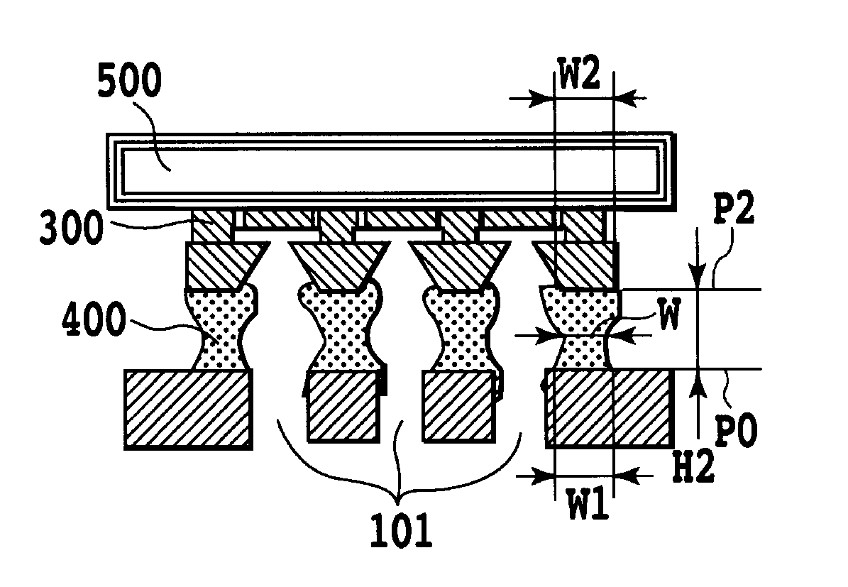
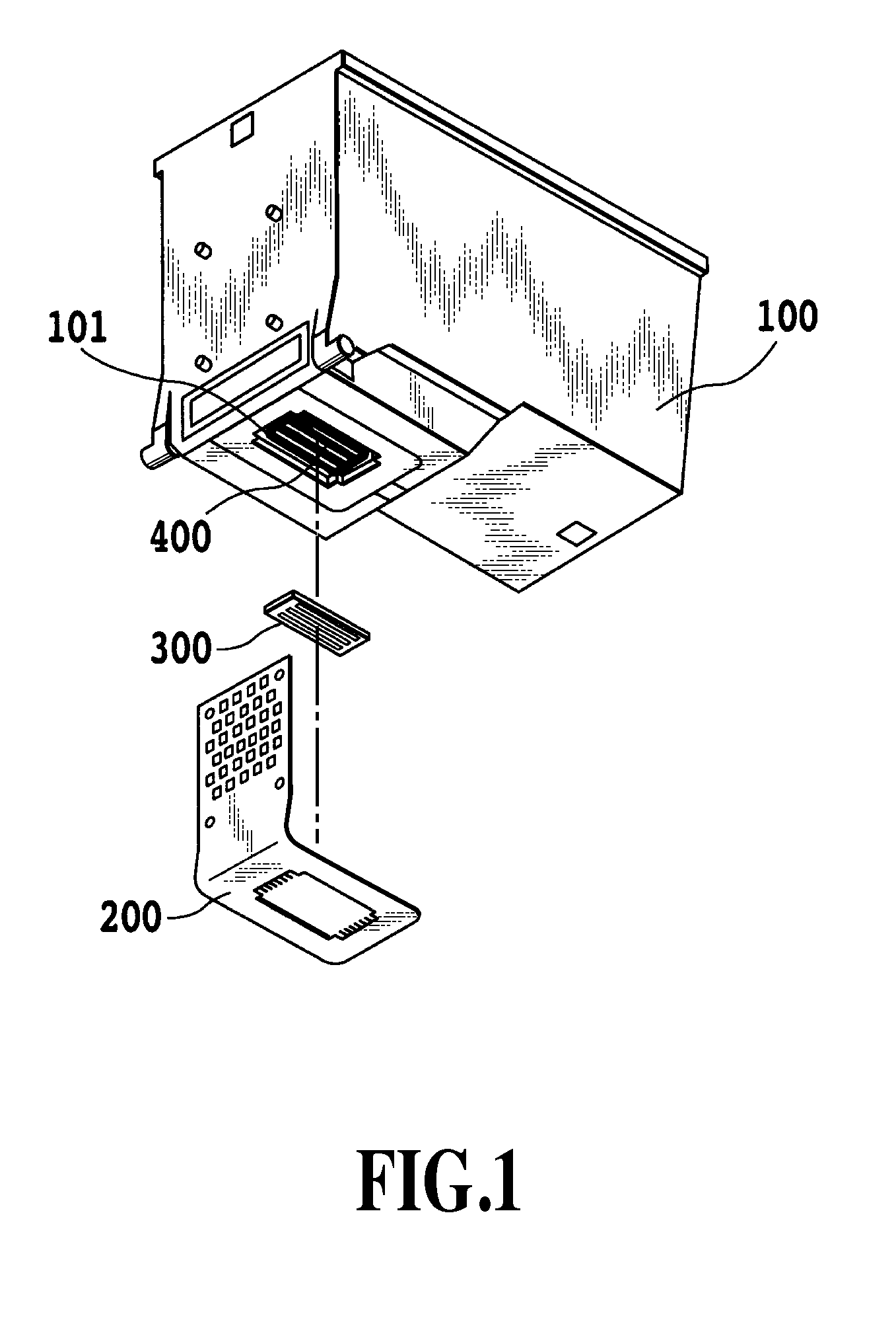
[0033]FIG. 1 is a perspective view showing an example of an overall construction of an ink jet print head according to this invention. Portions similar to those of the conventional print head are assigned like reference numerals and their explanations are omitted here.

[0034]In the print head of this example, a lead portion of an electric wiring tape 200 is electrically connected to electrode terminals of a chip-like print element substrate 300. The print element substrate 300 is bonded with an adhesive 400 to a surface of a support member 100 at areas surrounding ink supply ports 101. The electrode terminals of the print element substrate 300 and exposed parts of the lead portion of the electric wiring tape 200 are sealed with a sealing agent.

[0035]In a step of bonding an ink introducing port forming surface 301A of the print element substrate 300 to an areas surrounding the ink supp...


PUM

PropertyMeasurementUnit
Widthaaaaaaaaaa

Abstract

An ink jet print head manufacturing method and an ink jet print head are provided in which a shape of an adhesive that bonds a support member and a print element substrate together is controlled to maintain a high level of ink ejection performance even if the print element substrate is reduced in size. The adhesive, after being disposed between the support member and the print element substrate, is elongated and then hardened. This process allows the shape of the adhesive to be controlled, securing a sufficient ink path between an ink supply port on the support member side and an ink introducing port on the print element substrate side.

Description

BACKGROUND OF THE INVENTION[0001]1. Field of the Invention[0002]The present invention relates to a method of manufacturing an ink jet print head in which an ink ejecting print element and a support member capable of supplying ink to the print element are bonded together with adhesive. The invention also relates to such an ink jet print head.[0003]2. Description of the Related Art[0004]An example of currently available ink jet print head has a construction as shown in FIG. 8, in which a support member 100 and a chip-like print element substrate 300 are bonded together with an adhesive 400 (see FIG. 9). The print element substrate 300 is bonded to areas surrounding ink supply ports 101 in the support member 100. The print element substrate 300 has a plurality of ejection openings formed therein to eject ink supplied from the ink supply ports 101 of the support member 100. The print element substrate 300 also has an electrothermal conversion element (heater) or a piezoelectric element ...

Claims


Application Information

Patent Timeline
IPC IPC(8): B41J2/175B32B37/02
CPCB41J2/1603B41J2/1623B41J2002/14362B41J2/17553B41J2/1753
Inventor YONEDA, ISAMU
Owner CANON KK
Why Eureka
Try Eureka