Projection display device, and speckle reduction element
Inactive Publication Date: 2009-12-17
PANASONIC CORP
View PDF6 Cites 28 Cited by
Summary
Abstract
Description
Claims
Application Information
AI Technical Summary
This helps you quickly interpret patents by identifying the three key elements:
Problems solved by technology
Method used
Benefits of technology
Benefits of technology
[0006]In view of the above conventional drawback, it is an object of the invention to provide a projection display device that enables to reduce the size of the projection display device, enhance reliability of the device, and reduce speckle noise, as well as a speckle reduction element.
[0009]In the above arrangement, unlike the conventional art, wherein an actuator is used to mechanically change the degree of diffusion, the degree of diffusion is electrically changed. This enables to miniaturize the projection display device, and enhance reliability of the device. Further, since the degree of diffusion of the laser light is temporally changed, speckle noise can be reduced.
[0012]In the above arrangement, unlike the conventional art, wherein an actuator is used to mechanically change the degree of diffusion, the degree of diffusion is electrically changed. This enables to miniaturize the projection display device, and enhance reliability of the device. Further, since the degree of diffusion of the laser light is temporally changed, speckle noise can be reduced.
Problems solved by technology
In the projection display device incorporated with the above laser light sources, generation of speckle noise has been a drawback.
Speckle noise is a random interference pattern resulting from interference of laser light reflected on a screen having fine convex and concave portions in the case where an image is formed on the screen by using laser light having a high interference property.
This may increase the size of the projection display device, or lower reliability of the device by wear of mechanical parts.
Method used
Image
Click on the blue label to locate the original text in one second.
Reading with bidirectional positioning of images and text.
Examples
first embodiment
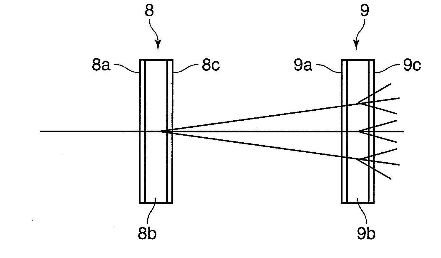
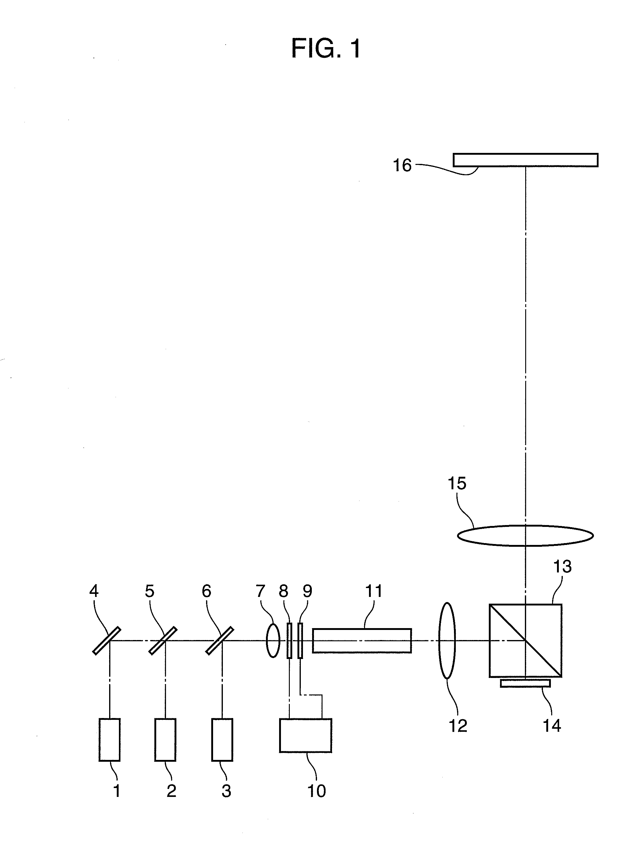
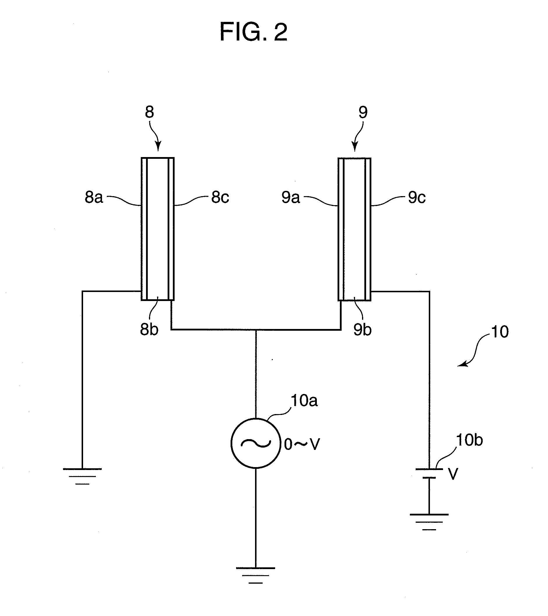
[0026]FIG. 1 is a diagram showing an arrangement of a projection display device in accordance with the first embodiment of the invention. Referring to FIG. 1, the projection display device includes a blue laser 1, a red laser 2, a green laser 3, a mirror 4, dichroic mirrors 5 and 6, a condenser lens 7, a first light diffusing element 8, a second light diffusing element 9, a drive circuit 10, a rod integrator 11, a lens 12, a polarized beam splitter 13, a spatial light modulation element 14, and a projection lens 15. The first light diffusing element 8, the second light diffusing element 9, and the drive circuit 10 constitute a speckle reduction element.
[0027]The blue laser 1 emits blue laser light, the red laser 2 emits red laser light, and the green laser 3 emits green laser light. A semiconductor laser is a preferred example of the blue laser 1 and the red laser 2. A solid-state laser incorporated with a SHG device is a preferred example of the green laser 3.
[0028]The mirror 4 ref...
second embodiment
[0048]In this section, a projection display device in accordance with the second embodiment of the invention is described. FIG. 7 is a diagram showing an arrangement of the projection display device in accordance with the second embodiment. Elements in FIG. 7 substantially identical or equivalent to those in FIG. 1 are indicated with the same reference numerals, and description thereof is omitted herein.
[0049]Referring to FIG. 7, the projection display device includes a blue laser 1, a red laser 2, a green laser 3, concave lenses 17a, 17b, and 17c, convex lenses 18a, 18b, and 18c, light diffusers 19a, 19b, and 19c, drive circuits 20a, 20b, and 20c, lenses 21a, 21b, and 21c, spatial light modulation elements 22a, 22b, and 22c, a color combination prism 23, and a projection lens 15.
[0050]The concave lens 17a and the convex lens 18a, the concave lens 17b and the convex lens 18b, and the concave lens 17c and the convex lens 18c respectively constitute beam expander optical systems. The ...
TECHNICAL FIELD[0001]The present invention relates to a projection display device using laser light, and a speckle reduction element for reducing speckle noise.BACKGROUND ART[0002]In recent years, as a high-output blue semiconductor laser has been commercialized, development of a projection display device incorporated with three primary colorlaser light sources has been progressed by using a red semiconductor laser, a green laser with a second harmonic generation device (hereinafter, abbreviated as “SHG device”), and the blue semiconductor laser. Use of a laser for emitting monochromatic laser light as a light source is advantageous in producing a projection display device with a wide reproducible color range, and a small electric power consumption. In the projection display device incorporated with the above laser light sources, generation of speckle noise has been a drawback. Speckle noise is a random interference pattern resulting from interference of laser light reflected on a ...
Claims
Application Information
Patent Timeline
Application Date:The date an application was filed.
Publication Date:The date a patent or application was officially published.
First Publication Date:The earliest publication date of a patent with the same application number.
Issue Date:Publication date of the patent grant document.
PCT Entry Date:The Entry date of PCT National Phase.
Estimated Expiry Date:The statutory expiry date of a patent right according to the Patent Law, and it is the longest term of protection that the patent right can achieve without the termination of the patent right due to other reasons(Term extension factor has been taken into account ).
Invalid Date:Actual expiry date is based on effective date or publication date of legal transaction data of invalid patent.

