Eureka AIR delivers breakthrough ideas for toughest innovation challenges, trusted by R&D personnel around the world.

Image encoding and decoding method and apparatus

a technology of encoding and decoding methods and apparatuses, applied in the field of encoding and decoding still images, can solve the problems of increasing prediction residual errors and consequently reducing encoding efficiency, and achieve the effect of high encoding efficiency and decoding

Inactive Publication Date: 2009-12-17
KK TOSHIBA
View PDF2 Cites 175 Cited by
  • Summary
  • Abstract
  • Description
  • Claims
  • Application Information

AI Technical Summary

Benefits of technology

[0011]It is an object of the present invention to provide a method and apparatus for image encoding having high encoding efficiency and decoding.

Problems solved by technology

Therefore, when correlation between the luminance of the pixels of the sub-block and the luminance of the left and upper pixels is low, a prediction residual error increases, and encoding efficiency consequently decreases.

Method used


Image

  • Image encoding and decoding method and apparatus
  • Image encoding and decoding method and apparatus
  • Image encoding and decoding method and apparatus

Examples


Embodiment Construction

[0087]An embodiment of the present invention will be described below with reference to the drawings.

[0088]

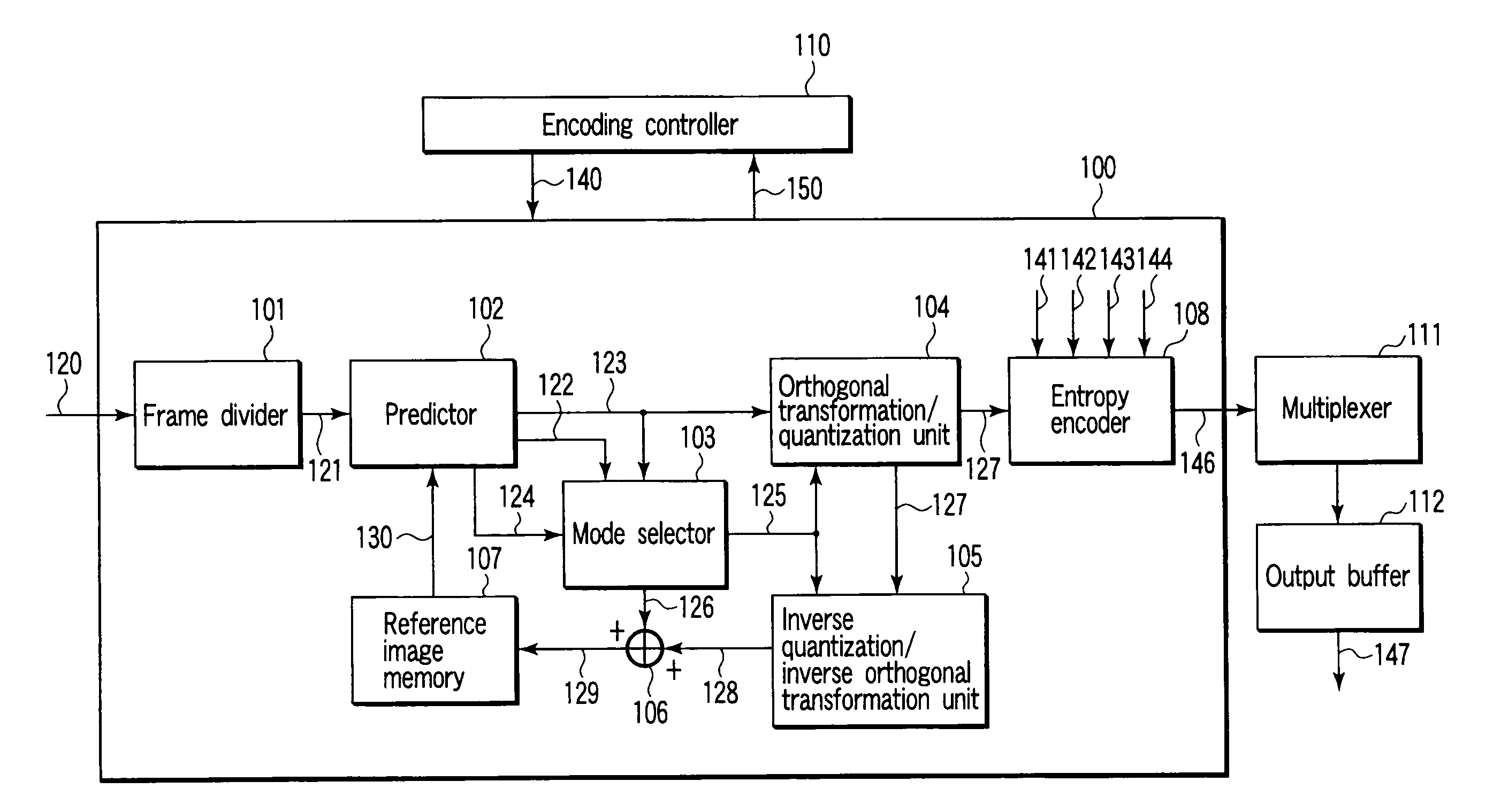
[0089]As shown in FIG. 1, in an image encoding apparatus according to an embodiment of the invention, an input image signal 120 of a moving image or a still image is input to an image encoder 100. The image encoder 100 has a frame divider 101, a predictor 102, a mode selector 103, an orthogonal transformation / quantization unit 104, an inverse quantization / inverse orthogonal transformation unit 105, an adder 106, a reference image memory 107, and an entropy encoder 108.

[0090]An encoding controller 110 gives encoding control information 140 to the image encoder 100 to control a whole of an encoding process of the image encoder 100 and properly receives feedback information 150 from the image encoder 100. The encoding control information 140 includes prediction mode index information (described later), block size switching information, prediction order switching information, predic...


PUM


Abstract

An image encoding apparatus includes a first selector selecting a prediction-order to sub-blocks obtained by further dividing pixel-blocks obtained by dividing a frame of an input-image-signal from predetermined prediction-orders, a second selector selecting, from prediction-modes regulating a manner of referring to an encoded-pixel when a first-prediction-signal of each-sub-block is generated with reference to the encoded-pixel, the number of prediction-modes used in prediction of the first-prediction-signal, a third selector selecting prediction-modes the number of which is the selected number from prediction-modes to use the prediction-modes in prediction of the first-prediction-signal, a generator generating the first-prediction-signal in the selected prediction order by using the selected prediction-modes the number of which is the selected number to generate a second-prediction-signal corresponding to the pixelblock, and an encoder encoding a prediction-residual-error-signal expressing a difference between an image-signal of the pixel-block and the second-prediction-signal to generate encoded data obtained by the prediction-encoding.

Description

TECHNICAL FIELD [0001]The present invention relates to a method and apparatus for encoding and decoding a moving or a still image.BACKGROUND ART [0002]In recent years, an image encoding method the encoding efficiency of which is considerably improved is recommended as ITU-T Rec.H.264 and ISO / IEC 14496-10 (to be referred to as H.264 hereinafter) in cooperation with ITU-T and ISO / IEC. In an encoding scheme such as ISO / IEC MPEG-1, 2, and 4, ITU-T H.261, and H.263, intra-frame prediction in a frequency region (DCT coefficient) after orthogonal transformation is performed to reduce a code amount of a transformation coefficient. In contrast to this, directional prediction (see Greg Conklin, “New Intra Prediction Modes”, ITU-T Q.6 / SG16 VCEG, VCEG-N54, September 2001) is employed to realize prediction efficiency higher than that of intra-frame prediction in ISO / IEC MPEG-1, 2 and 4.[0003]In an H.264 high profile, intra-frame prediction schemes of three types are regulated to a luminance sign...

Claims


Application Information

Patent Timeline
Patent Type & Authority Applications(United States)
IPC IPC(8): G06K9/36G06K9/46H04N7/32
CPCH04N19/11H04N19/119H04N19/147H04N19/19H04N19/593H04N19/70H04N19/103H04N19/105H04N19/51
Inventor SHIODERA, TAICHIROTANIZAWA, AKIYUKICHUJOH, TAKESHI
Owner KK TOSHIBA
Why Eureka
Eureka Blog
Learn More