Eureka AIR delivers breakthrough ideas for toughest innovation challenges, trusted by R&D personnel around the world.

Imaging apparatus and control method thereof

a technology of image quality and control method, applied in the field of image quality degradation and control method, can solve the problems of image quality degradation due to compression, and achieve the effect of suppressing image quality degradation and high encoding efficiency

Active Publication Date: 2018-02-01
CANON KK
View PDF4 Cites 2 Cited by
  • Summary
  • Abstract
  • Description
  • Claims
  • Application Information

AI Technical Summary

Benefits of technology

The present invention provides a technique for efficient encoding of RAW image data obtained by imaging with high efficiency and without compromising image quality. This is achieved by converting the RAW image data into multiple planes, generating subbands, and non-linearly converting the coefficient data to suppress the loss of information in dark portions. The encoding unit quantizes the coefficient data and applies efficient encoding methods to achieve high efficiency. Overall, the invention allows for efficient and high-quality image data encoding.

Problems solved by technology

However, depending on the shooting condition, image quality degradation may occur due to compression.
Therefore, using the image data at the time of encoding, which was recorded before the developing process, can cause image quality degradation even if optimal quantization is performed in accordance with the characteristics of the human visual system.

Method used


Image

  • Imaging apparatus and control method thereof
  • Imaging apparatus and control method thereof
  • Imaging apparatus and control method thereof

Examples


first embodiment

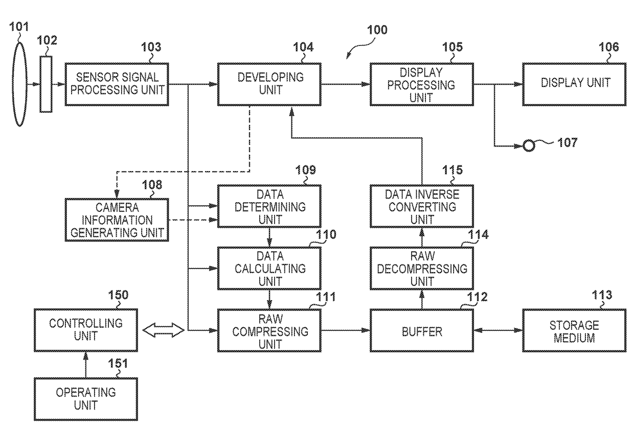
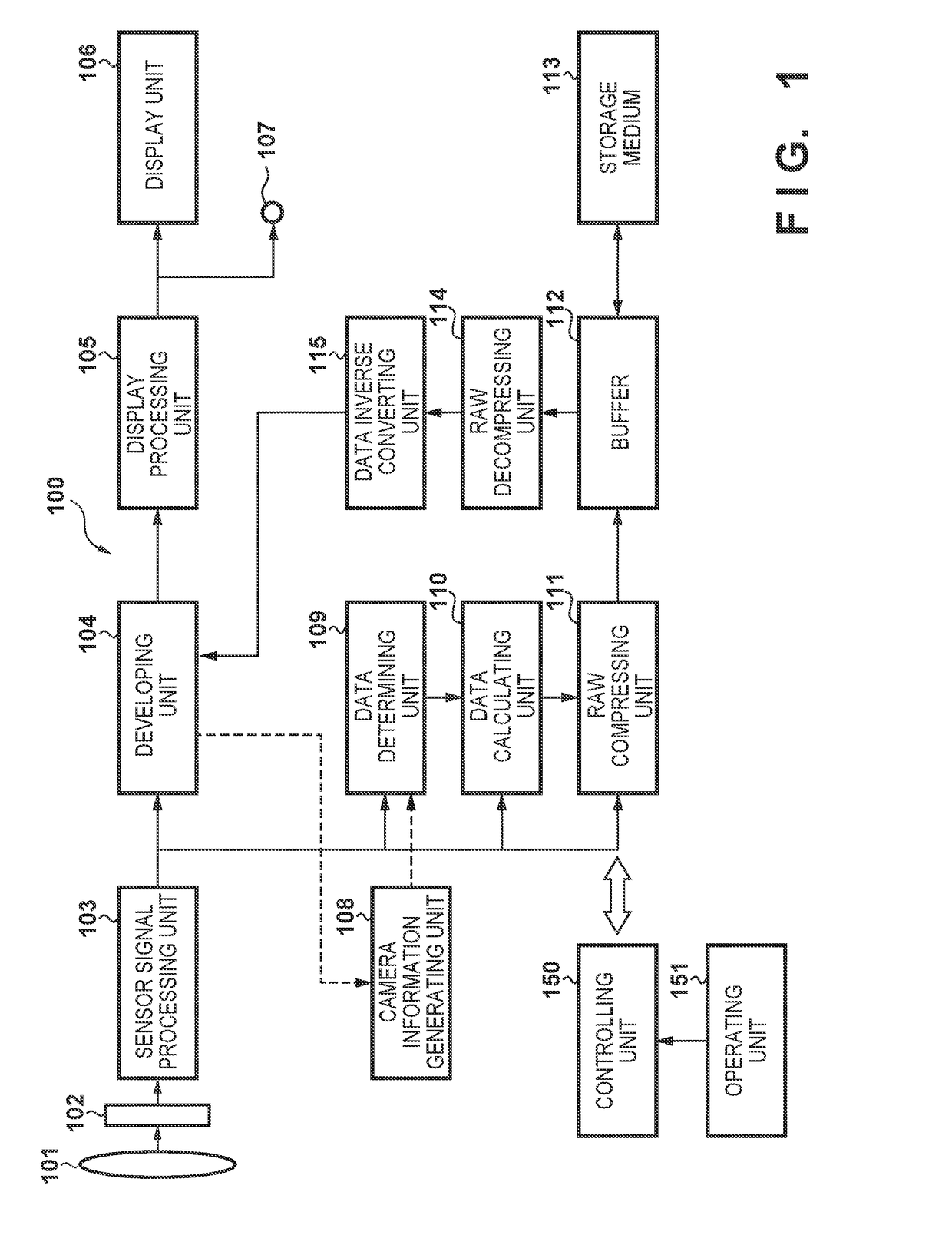
[0024]FIG. 1 is a block diagram showing an example of the arrangement of an imaging apparatus 100 according to the first embodiment. In FIG. 1, a controlling unit 150 controls the overall apparatus and includes a CPU, a ROM storing programs to be executed by the CPU, and a RAM which is used as a work area. This controlling unit 150 is connected to an operating unit 151 that accepts instruction inputs from a user.

[0025]In the arrangement shown in FIG. 1, when the user inputs a shooting instruction via the operating unit 151, an optical image of an object serving as an imaging target is formed on an image sensor unit 102 via an optical system 101 under the control of the controlling unit 150. The image sensor unit 102 generates electrical signals representing the intensity of light transmitted through red, green, and blue (RGB) color filters arrayed on corresponding pixels.

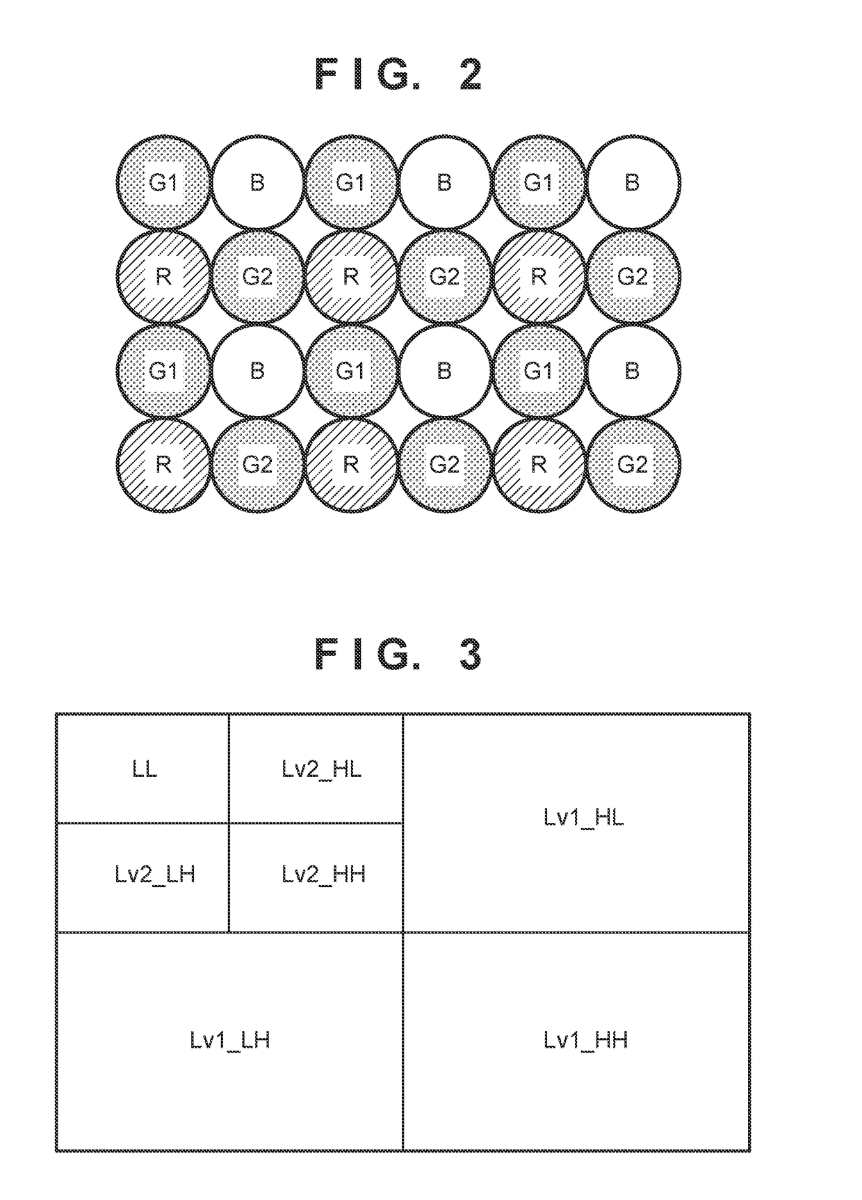
[0026]FIG. 2 is an example of the color filters arranged on the image sensor unit 102 and represents the pixel ar...

second embodiment

[0068]FIG. 10 is a block diagram showing the arrangement of an imaging apparatus according the second embodiment. The same reference numerals will denote the same components as those used in FIG. 1 of the above-described first embodiment. In addition, since the overall processing is the same as that described above, only parts having different processes will be described below.

[0069]A plane converting unit 216 generates, from the RAW image data input from sensor signal processing unit 103, a total of four planes comprised of a Y plane representing luminance and three planes representing color differences C1, C2, and C3. More specifically, the relationship between the aforementioned four planes and the R, B, G1, and G2 planes which are directly separable from the RAW image data can be shown as follows.

Y=(R+B+G1+G2)4C1=R-G1C2=B-G2C3=R+G12-B+G22

[0070]Note that the four planes comprised of one plane representing the luminance Y and three planes representing the color differences C1, C2,...

third embodiment

[0077]The arrangement of an imaging apparatus according to the third embodiment is the same as that of FIG. 1 in the first embodiment. In the third embodiment, it is possible to perform a non-linear conversion process on each plane or subband without having to perform color conversion processing on each plane. Furthermore, non-linear information can be represented in various ways.

[0078]FIG. 13 shows the data structure of non-linear information according to the third embodiment. In the same manner as in FIG. 9, there is an identification number, and then a polynomial type is described. In the same manner as in the first embodiment, “Ploytype2” has been set as equation (2). A coefficient “e” is stored in the next position. In addition, if the non-linear count of a plane header portion is 2 or larger, the intersection point information is stored as “PI”. This is described as an input value “x” and an output value “y”. Next, after a “Point type” is described, a transformation is formed ...


PUM


Abstract

This invention performs encoding with high encoding efficiency while suppressing image quality degradation when RAW image data obtained by imaging is to be encoded. Hence, an imaging apparatus that encodes an image captured by an image sensor includes a plane converting unit configured to convert RAW image data of a Bayer array obtained by the image sensor into a plurality of planes each comprised of a pixel of a single component, a frequency transforming unit configured to generate a plurality of subbands by frequency-transforming each of the obtained planes, a non-linear converting unit configured to non-linearly convert coefficient data forming each of the subbands based on camera information related to imaging in the imaging apparatus, and an encoding unit configured to encode by quantizing the coefficient data obtained by the non-linear conversion by the non-linear converting unit.

Description

BACKGROUND OF THE INVENTIONField of the Invention[0001]The present invention relates to an imaging apparatus and more particularly a technique of handling a RAW image of a still image or a moving image.Description of the Related Art[0002]In an imaging apparatus, raw image information (RAW image) captured by an image sensor undergoes a debayer process (demosaicing process) and is converted into signals formed of luminance and color differences, and a so-called developing process such as noise removal, optical distortion correction, optimization of an image, and the like is performed on each signal. Then, the imaging apparatus compression-encodes the luminance and color difference signals that have been developed and records the resultant signal in a storage medium.[0003]On the other hand, there exists an imaging apparatus that can record a RAW image. The RAW image of such an apparatus is advantageous in that correction and degradation of an original image obtained immediately after a...

Claims


Application Information

Patent Timeline
Patent Type & Authority Applications(United States)
IPC IPC(8): H04N9/73H04N5/77G06K9/36H04N9/82H04N5/232H04N9/804
CPCH04N9/735H04N5/23229H04N5/772G06K9/36H04N9/8205H04N9/8042G06T2207/20064H04N23/10H04N25/134H04N23/95G06T9/007H04N23/88H04N23/80
Inventor OISHI, AKIHIRO
Owner CANON KK
Why Eureka
Eureka Blog
Learn More