Direction Finding Antenna Systems and Methods for Use Thereof

a direction finding and antenna technology, applied in direction finders using radio waves, instruments, reradiation, etc., can solve the problems of large signal strength difference, unsuitable portable or casual use, and no direction finding antenna system on the market that is compa

Inactive Publication Date: 2009-12-24
HONG KONG APPLIED SCI & TECH RES INST
View PDF8 Cites 24 Cited by
  • Summary
  • Abstract
  • Description
  • Claims
  • Application Information

AI Technical Summary

Benefits of technology

[0006]Various embodiments of the present invention are directed to a systems and methods which include at least two antenna elements providing a first and second antenna patterns, the antenna elements configured such that the greatest difference in received signal strength of the two antenna patterns occurs at a null of one of the antenna patterns.

Problems solved by technology

Highly directive antenna systems, however, are often large and unwieldy, thereby causing them to be unfit for portable or casual use.
However, multiple nulls means that there is more than one azimuthal direction that shows a large signal strength difference.
Currently there is no direction finding antenna system on the market that is compact and provides for unequivocal indications of azimuthal direction of a transmitter.

Method used


Image

  • Direction Finding Antenna Systems and Methods for Use Thereof
  • Direction Finding Antenna Systems and Methods for Use Thereof
  • Direction Finding Antenna Systems and Methods for Use Thereof

Examples


Embodiment Construction

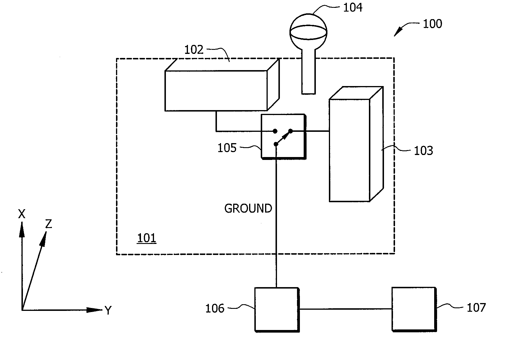
[0023]FIG. 1 is an illustration of exemplary antenna system 100 adapted according to one embodiment of the invention. Antenna system 100 includes two antenna elements 102 and 103. Between antenna elements 102 and 103 is parasitic element 104, and also there is switch 105 that is used to select signals from one antenna element 102 / 103 at a time. In this particular example, the various components are disposed on PCB 101, which also hosts ground plane 106 on a lower layer, the outline of which is indicated by a dashed line. Parasitic element 104 is disposed so as to provide an RF trap on antenna 103, thereby creating a single null on the direction of a line between the parasitic element and antenna 103.

[0024]System 100 also includes RF module 106 in communication with switch 105 to receive the signals from antennas 102 and 103. In this embodiment, RF module 106 has a control circuit operating switch 105 to switch between receiving the signals of antenna 102 and antenna 103. Switch 105 ...


PUM


Abstract

An antenna system comprising a first antenna element, a second antenna element, and a parasitic element, wherein the parasitic element is arranged with regard to the first antenna element and the second antenna element such that a greatest difference in gain between respective antenna patterns of the first and second antenna elements occurs at a null of the pattern of the first antenna element.

Description

TECHNICAL FIELD[0001]The present disclosure is directed to direction finding antenna systems and, more specifically, to direction finding antenna systems employing a plurality of antennas.BACKGROUND OF THE INVENTION[0002]Antenna systems come in a variety of forms. Of particular popularity now are systems built on Printed Circuit Boards (PCBs). For example, a PCB patch antenna includes a radiating portion that is disposed on a layer of a PCB and a ground plane that is disposed on another layer either above or below the radiating portion (where “above” and “below” refer to positions in the stack of layers). Since the radiating portion of a patch antenna utilizes the ground plane, it is called a grounded antenna. Other antenna elements are not oriented above or below a ground plane and are referred to as ungrounded antennas. A Planar Inverted F Antenna (PIFA) can be made from some patch antennas by shorting an end of a patch element to ground. Many antenna elements are associated with ...

Claims


Application Information

Patent Timeline
Patent Type & Authority Applications(United States)
IPC IPC(8): G01S13/00H01Q21/00
CPCG01S3/043G01S3/046G01S3/18H01Q21/28H01Q1/38H01Q9/42G01S3/40
Inventor MAK, ANGUS C. K.ROWELL, CORBETT R.MAK, CHI-LUN
Owner HONG KONG APPLIED SCI & TECH RES INST
Why Eureka
Try Eureka