
Distributable Quantum Relay Architecture

a quantum relay and distributed technology, applied in the field of quantum teleportation, can solve problems such as failures and inability to easily lend themselves to practical application in real networks, and achieve the effect of increasing the indistinctness of photon pairs

Active Publication Date: 2009-12-24
PERSPECTA LABS INC
View PDF18 Cites 27 Cited by
  • Summary
  • Abstract
  • Description
  • Claims
  • Application Information

AI Technical Summary

Benefits of technology

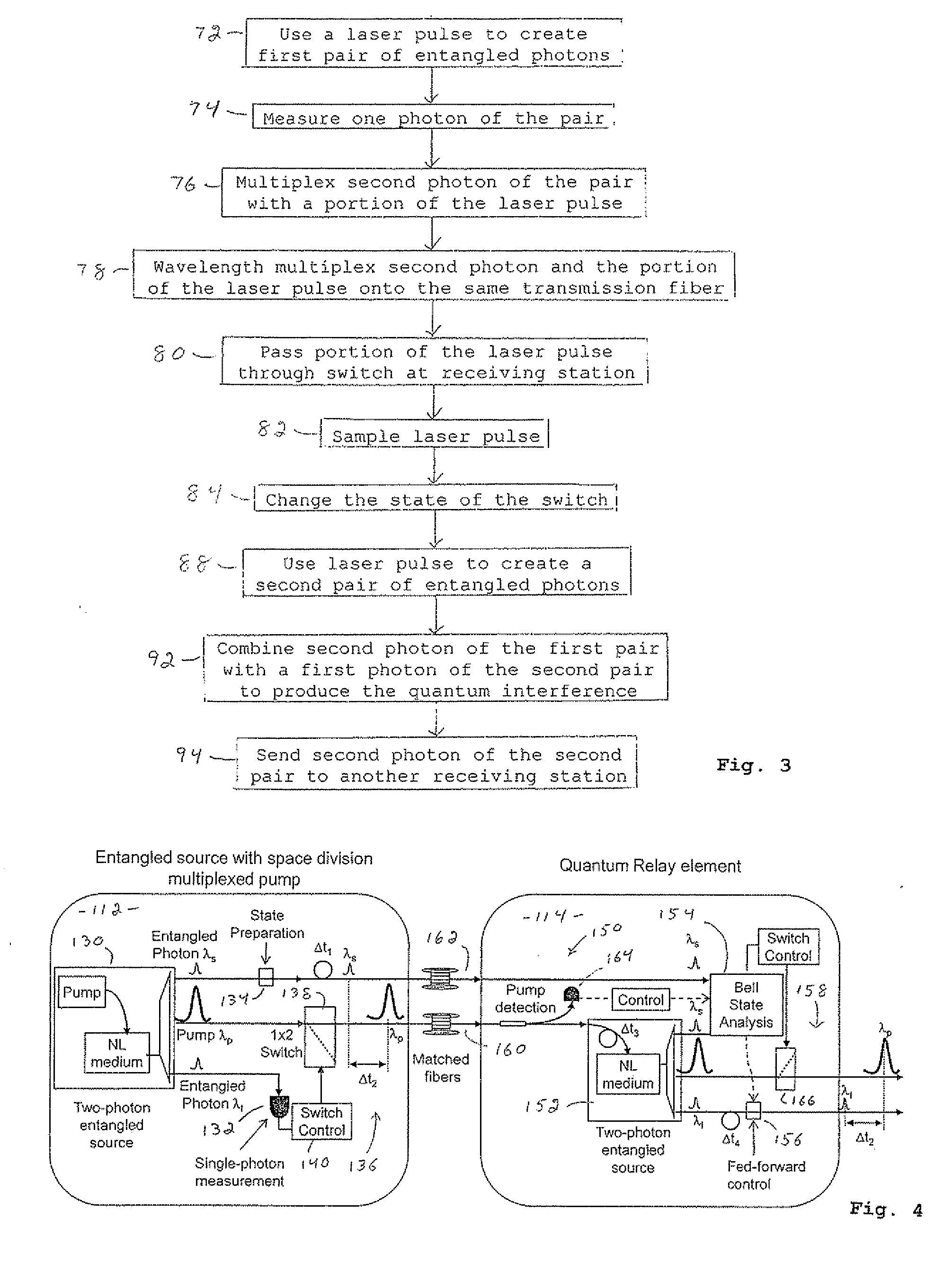
[0016]The preferred embodiment of the invention, described in detail below, uses time and wavelength division multiplexing to enable the residual portion of a laser pump pulse, already used to create an initial entangled photon pair, to be distributed to a remote relay site, on the same optical fiber as a photon from that initial pair. At that remote site, the pump pulse can be amplified, attenuated and frequency filtered and used to locally create the second entangled photon pair that is required for quantum teleportation. Distribution of the pump pulse from the first station to the successive relay stations can increase indistinguishability of the photon pairs used for teleportation at the relays from the initial photon whose quantum state is being teleported.

Problems solved by technology

However, because most implementations utilize an ultrashort laser pump to create entangled photons, this approach normally requires the two pairs to be created in close spatial proximity, e.g., on the same optical table, which does not easily lend itself to practical application in realistic networks.
Such a solution fails when the fluctuations that are to be stabilized occur on a time scale comparable to the time it takes for information to travel from distant stations.

Method used


Image

  • Distributable Quantum Relay Architecture
  • Distributable Quantum Relay Architecture
  • Distributable Quantum Relay Architecture

Examples


Embodiment Construction

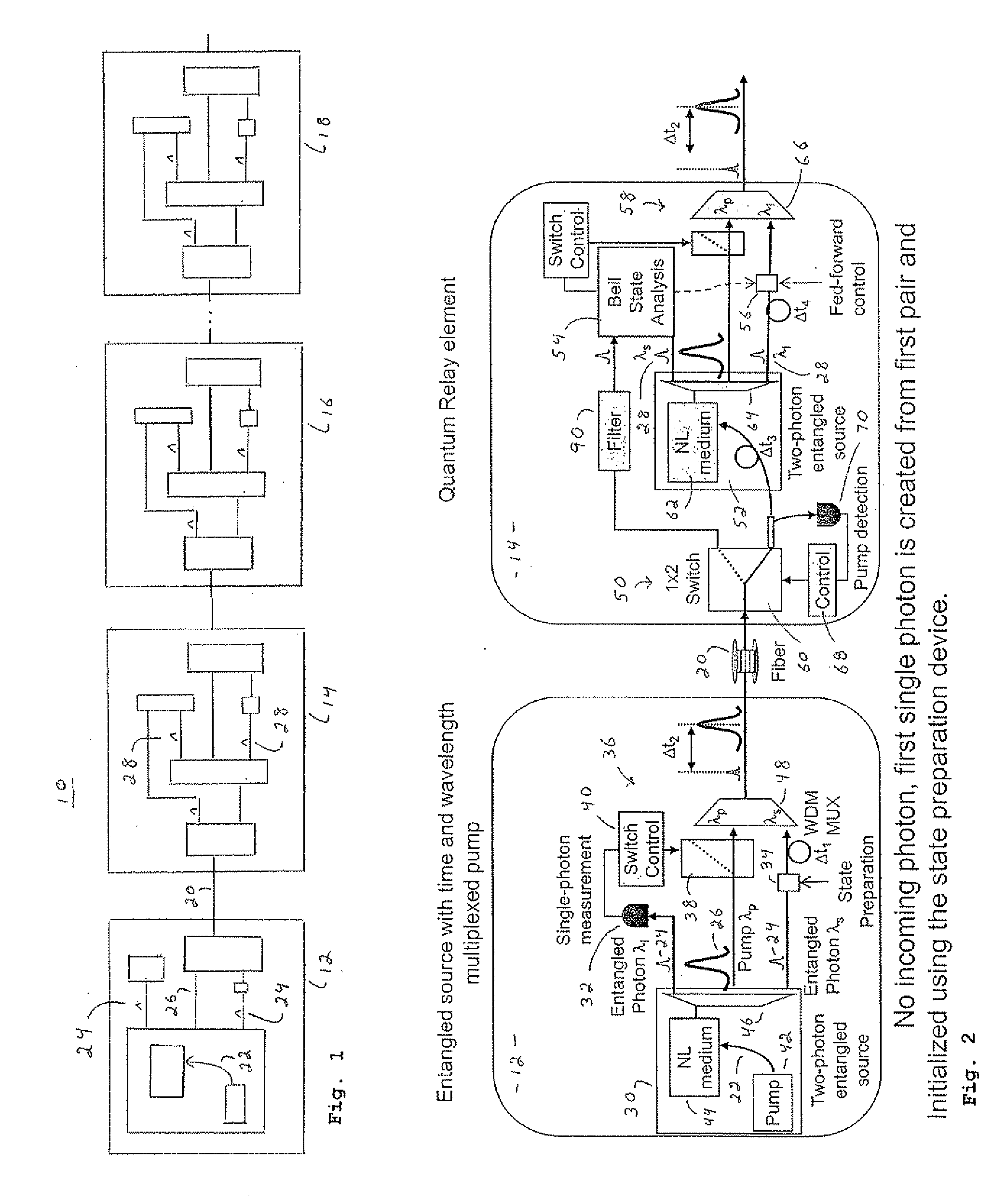
[0023]The present invention, in one embodiment, provides a distributed quantum relay architecture in which time and wavelength division multiplexing enables a laser pump pulse, already used to create an initial entangled photon pair, to be distributed to a remote relay site, on the same optical fiber as a photon from that initial pair. At that remote site, the pump pulse is amplified as needed and used to locally create the second entangled photon pair that is required for quantum teleportation.

[0024]FIG. 1 shows an architecture 10 in accordance with an embodiment of the invention. This architecture includes a multitude of stations 12, 14, 16, 18, connected together in series by optical fiber 20. This multitude of stations includes a first station 12, and a plurality of relay stations 14, 16, 18.

[0025]Generally, in architecture 10, first station 12 is provided for using a laser signal 22 to generate a first pair of entangled photons, represented at 24, and for measuring a state of a...


PUM


Abstract

A distributed quantum relay architecture is disclosed. In one embodiment of this architecture, time and wavelength division multiplexing are used to enable a laser pump pulse, already used to create an initial entangled photon pair, to be distributed to a remote relay site, on the same optical fiber as a photon from that initial pair. At that remote site, the pump pulse is amplified and used to locally create the second entangled photon pair that is required for quantum teleportation. This embodiment enables the placement of quantum repeater stations at remote locations without complicated dedicated channels to distribute the pump or electronics. In addition, as lasers are generally among the most expensive components, a significant cost savings is gained, in this embodiment, by using only one pump laser instead of two (or more) as in previous quantum teleportation efforts.

Description

CROSS-REFERENCE TO RELATED APPLICATION[0001]This application claims the benefit of provisional application No. 61 / 074,194, filed Jun. 20, 2008, the disclosure of which is herein incorporated by reference in its entirety.FIELD OF THE INVENTION[0002]The present invention generally relates to quantum teleportation, and more specifically, to an architecture enabling the use of widely distributed quantum relay or repeater stations along a fiber communications link.BACKGROUND OF THE INVENTION[0003]Quantum teleportation, which utilizes entanglement, is a critical technique for enabling quantum relays and quantum repeaters. In quantum teleportation an incoming qubit (e.g., a single photon), typically in an unknown quantum state, is combined with one half of a two-qubit (e.g., two-photon) entangled pair, and a Bell-state measurement is performed. The result of this measurement is then fed forward to apply an appropriate unitary transformation to the third qubit (that was originally part of t...

Claims


Application Information

Patent Timeline
Patent Type & Authority Applications(United States)
IPC IPC(8): H04B10/00
CPCH04B10/30H04L9/0855H04B10/70
Inventor PETERS, NICHOLAS A.CHAPURAN, THOMAS E.RUNSER, ROBERTGOODMAN, MATTHEW S.
Owner PERSPECTA LABS INC
Learn More