Vented cutting head body for abrasive jet system

a jet system and cutting head technology, applied in the field of abrasive jet systems, can solve the problems of abrasive delivery into the mixing chamber having a tendency to move upstream, damage to the jewel orifice holder, and abrasive may slowly accumulate on the upstream surfaces of the jewel orifi

Active Publication Date: 2009-12-24
FLOW INT
View PDF21 Cites 38 Cited by
  • Summary
  • Abstract
  • Description
  • Claims
  • Application Information

AI Technical Summary

Benefits of technology

[0007]An abrasive jet system, in some embodiments, has a nozzle assembly and a venting system for controlling the flow of media, such as abrasive, within the nozzle assembly. The venting system can protect various components of the nozzle system from the abrasive.

Problems solved by technology

Abrasive delivered into the mixing chamber has a tendency to move upstream through the cutting head assembly towards the jewel orifice.
The pressure differential often leads to abrasive movement that may result in the abrasive striking and causing damage to a jewel orifice holder supporting the jewel orifice.
Abrasive may slowly accumulate on the upstream surfaces of the jewel orifice.
The picked-up abrasive may quickly damage the jewel orifice, resulting in malfunctioning and / or significantly impaired performance of the cutting head assembly.
Unfortunately, the downtime may significantly reduce the productivity of the abrasive jet system.

Method used


Image

  • Vented cutting head body for abrasive jet system
  • Vented cutting head body for abrasive jet system
  • Vented cutting head body for abrasive jet system

Examples


Embodiment Construction

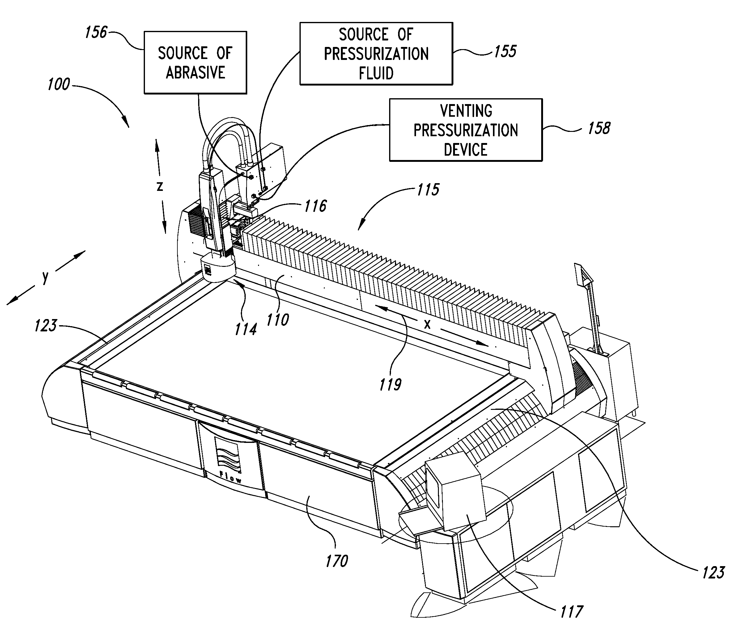
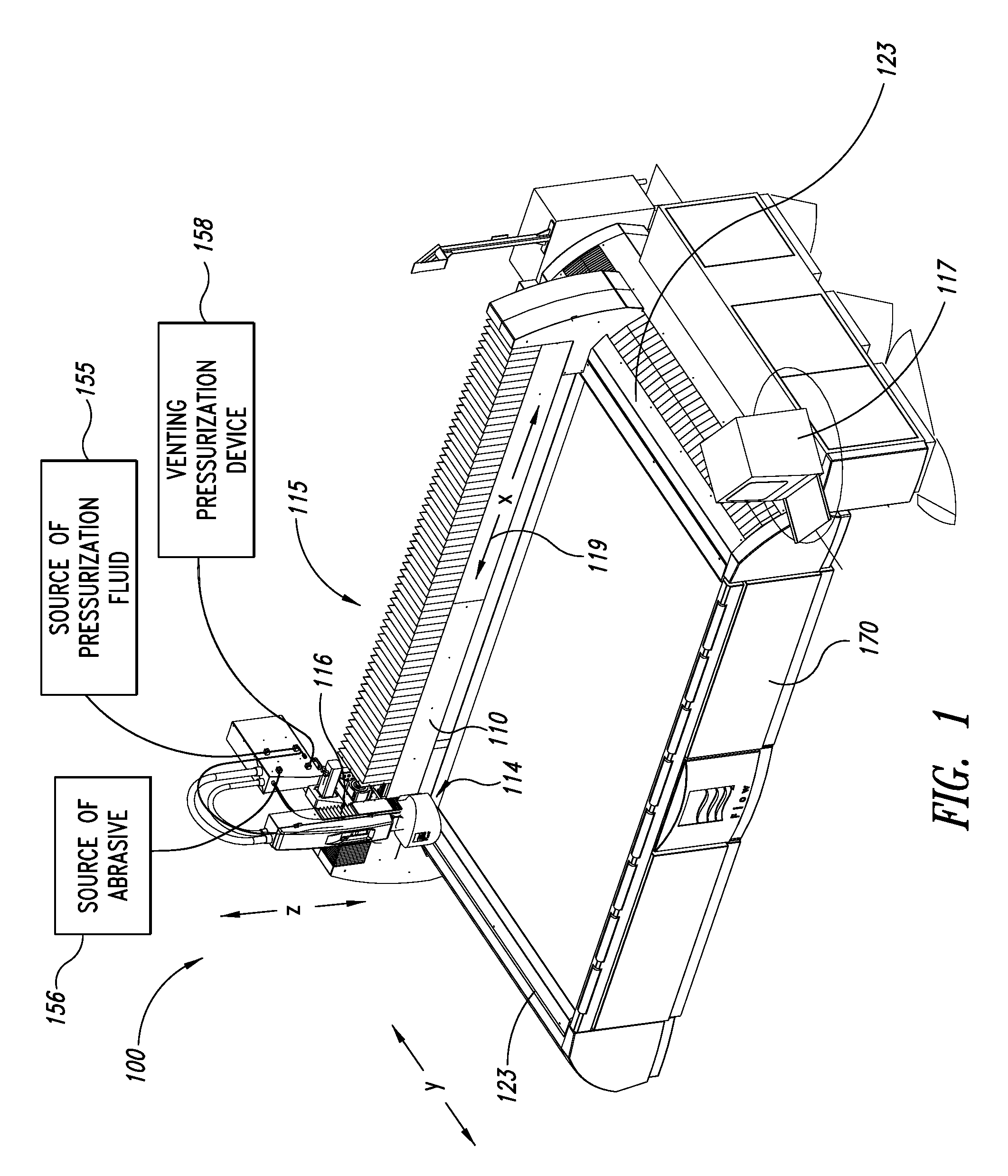
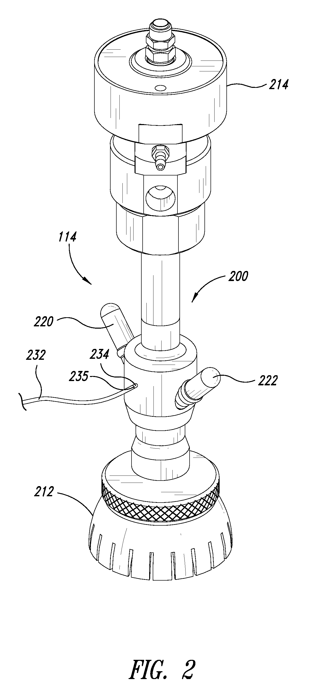
[0024]The following description relates to abrasive jet systems, assemblies, and subcomponents, for generating and delivering abrasive jets suitable for cleaning, abrading, cutting, milling, or otherwise processing workpieces. An abrasive jet system can have a nozzle assembly and a venting system for controlling the flow of abrasive within the nozzle assembly. The venting system can include, without limitation, one or more vents for regulating the pressure within at least a portion of the nozzle assembly to minimize, limit, or substantially eliminate physical interaction between the abrasive and an upstream component. The vents can be positioned between an orifice mount retaining a jewel orifice and an internal mixing region in which abrasive is mixed with a fluid jet. The vents, in some embodiments, can be used to increase or decrease the pressure upstream of a mixing region to protect a wide range of different components that are upstream of the mixing region.

[0025]Unless the cont...


PUM

PropertyMeasurementUnit
diameteraaaaaaaaaa
pressureaaaaaaaaaa
pressureaaaaaaaaaa

Abstract

An abrasive waterjet assembly has a cutting head assembly with a venting system for controlling the flow of abrasive within a cutting head body. The venting system includes one or more vents for regulating the pressure within a cutting head body to minimize, limit, or substantially eliminate any abrasive from reaching a jewel orifice. The vents include venting ports positioned between an orifice mount that retains the jewel orifice and a mixing region in which abrasive is mixed with a fluid jet produced by the jewel orifice. An isolator retained in the cutting head body further inhibits the upstream flow of abrasive, if any.

Description

BACKGROUND[0001]1. Technical Field[0002]The present invention relates generally to abrasive jet systems and, in particular, to abrasive jet systems having a vented cutting head body.[0003]2. Description of the Related Art[0004]Conventional abrasive jet systems are used to process workpieces by pressurizing fluid and then delivering the pressurized fluid against a workpiece. Abrasive jet systems produce high-pressure abrasive fluid jets (commonly referred to as abrasive jets) suitable for cutting through hard materials. High-pressure fluid can flow through a jet-forming jewel orifice of a cutting head assembly to form a high-pressure fluid jet into which abrasive particles are entrained. The high-pressure abrasive fluid jet is discharged from the cutting head assembly towards the workpiece.[0005]The abrasive and the fluid jet are often mixed together in a mixing chamber within the cutting head assembly. Abrasive delivered into the mixing chamber has a tendency to move upstream throug...

Claims


Application Information

Patent Timeline
Patent Type & Authority Applications(United States)
IPC IPC(8): B24B1/00B05B7/04
CPCB24C1/045B24C7/0076B24C7/0061B24C5/02
Inventor HASHISH, MOHAMED
Owner FLOW INT
Why Eureka
Try Eureka