Grinding and honing fixture with clamping jaws

Active Publication Date: 2009-12-24
CLAY TYMEN
View PDF20 Cites 14 Cited by
  • Summary
  • Abstract
  • Description
  • Claims
  • Application Information

AI Technical Summary

Benefits of technology

[0014]In an exemplary version of this jig, the adjustment mechanism comprises a plurality of adjustable screws distributed about a central pivot point of the ro

Problems solved by technology

However, in the past, it has generally required considerable skill for a person to sharpen such tools with a microbevel without causing any damage to the blade.
This is particularly true for a longer blade edge of two, three or more inches since it can be difficult to hold the blade at the correct orientation both for the grinding step and the honing step.
Although this known jig set may be satisfactory for forming the micro-bevel on the blade, it is not well suited for creating or grinding the basic bevel angle for the tool prior to the honing operation.
Although the above described grinding and honing apparatus works satisfactory for its intended purpose and can be used for both grinding and honing, there are some aspects of the apparatus which can cause difficulty for some users.
For example, the clamping mechanism of this known apparatus can make it difficult to sharpen a short tool or blade.
In addition there is no provision in this apparatus for self squaring of the tool or blade in the clamping mechanism, thus necessitating extra care to ensure that the tool or blade is properly oriented in the clamping mechanism.
Furthermore, it can be difficult to set the blade in the clamping mechanism so that it extends parallel to the grinding surface of the grinding wheel as desired without having to make careful, time consuming adjustments to the position of the blade in the clamping mechanism or without manufacturing the apparatus to very precise tolerances.

Method used


Image

  • Grinding and honing fixture with clamping jaws
  • Grinding and honing fixture with clamping jaws
  • Grinding and honing fixture with clamping jaws

Examples


Embodiment Construction

)

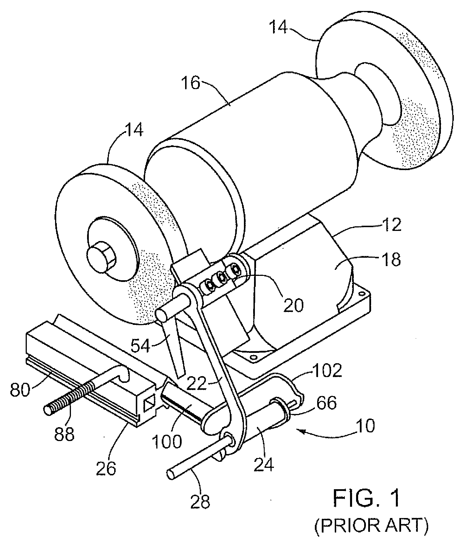
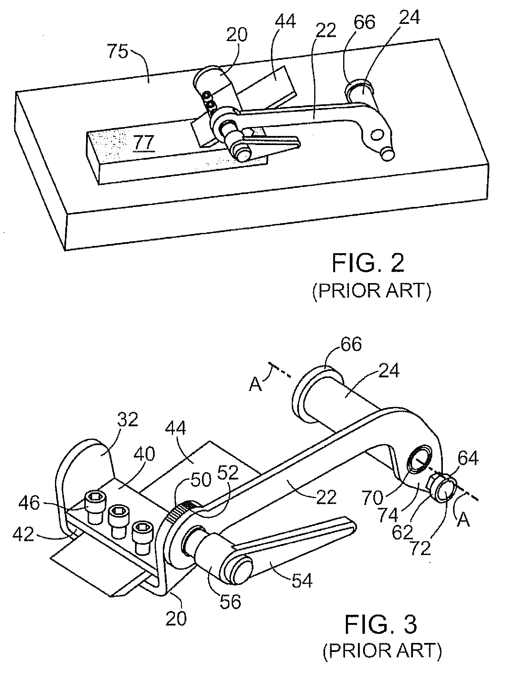
[0031]FIGS. 1 to 5 illustrate a prior art grinding and honing fixture 10 and illustrate both its construction and use. This known fixture 10 can be mounted on a bench or other suitable support surface next to a standard grinding machine 12 which can have one or two grinding wheels 14. In a known manner, the wheels are rotated at a high rate of speed by a motor such as the illustrated electrical motor 16. The motor can be mounted on a rigid machine base 18 which can be mounted on the work bench or other suitable support. The grinding wheels are made of a highly abrasive material suitable for grinding the blade of a metal tool.

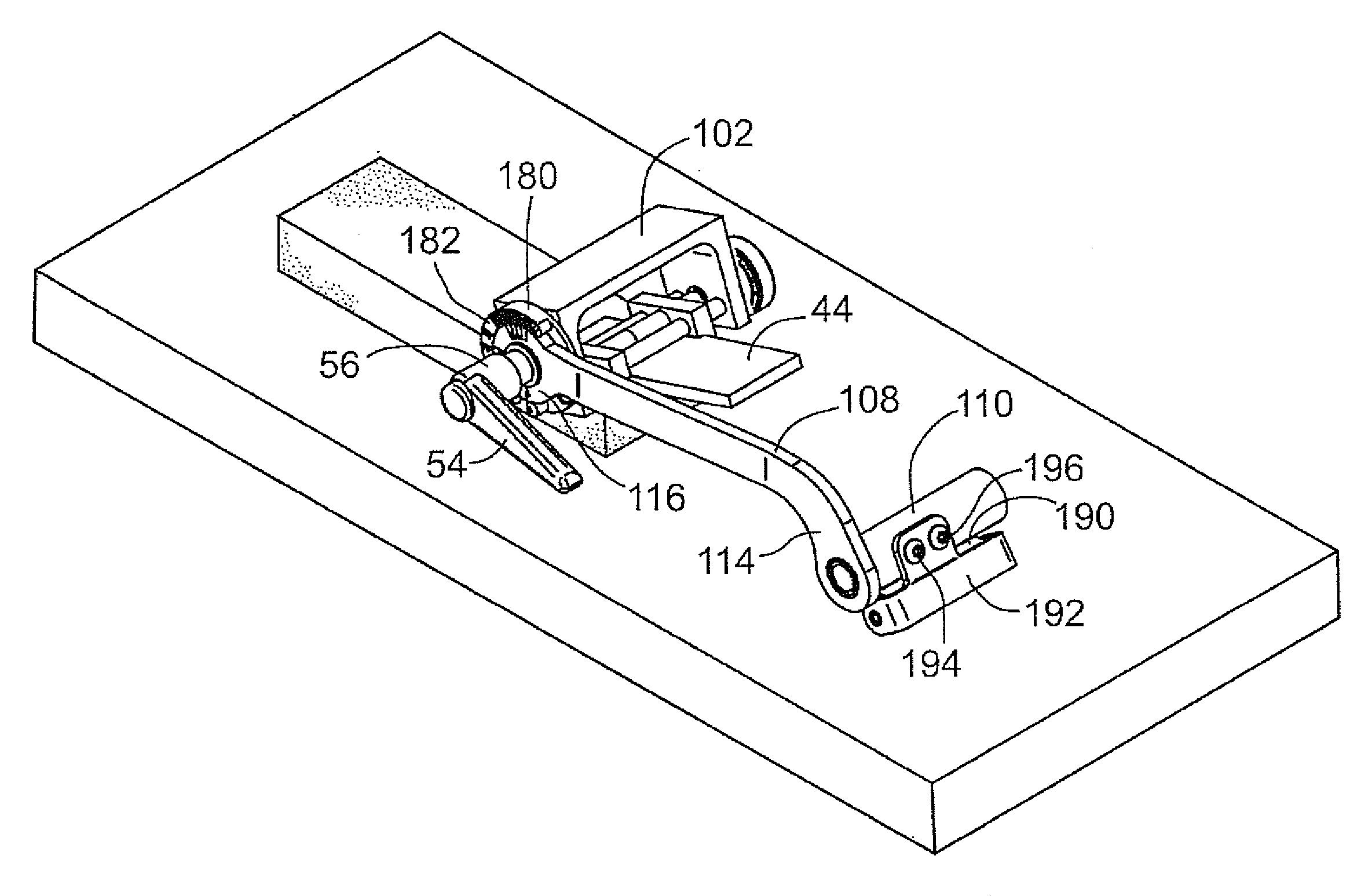
[0032]The known fixture 10 includes a clamping mechanism 20 able to clamp the tool or tool blade for the grinding operation, a pivotal, elongate arm 22 on which the clamping mechanism is mounted, and a tubular support member 24 extending from and connected to the arm. The fixture 10 also includes a mounting bar device 26 which is only used when the fixture is b...


PUM

PropertyMeasurementUnit
Lengthaaaaaaaaaa
Angleaaaaaaaaaa

Abstract

A blade holding jig arrangement for either grinding or honing a blade including a mounting bracket assembly with an elongate guide bar and a device for rigidly supporting the guide bar. A support arm can be pivotally mounted on the guide bar by means of a tubular support mounted on one end of the arm and extending perpendicular thereto. The guide bar extends through a passageway in the tubular support. The support arm can be moved along the guide bar for grinding. A clamp unit for clamping a blade includes a U-bracket with two legs and two clamping jaws adjustably mounted on the U-bracket between the legs. The clamp unit is attached to an end section of the arm remote from the one end of the arm. The clamping jaws can be moved towards one another in order to clamp the blade.

Description

CROSS-REFERENCE TO RELATED APPLICATION[0001]This application claims priority of Canadian Patent Application No. 2,635,614 filed Jun. 23, 2008.BACKGROUND OF THE INVENTION[0002]This invention relates to fixtures and devices for holding a blade of a tool such as a chisel or plane iron, for purposes for grinding or honing the blade.[0003]A tool having a blade must be sharpened from time to time in order for it to work properly and efficiently. A wide variety of tools with blades that require sharpening are known and these include chisels used in woodworking and plane irons used in planning tools. The width of the blade to be sharpened can vary between less than one half inch to two to three inches or more. Generally, the sharpening operation can include the basic steps of grinding a basic bevel angle on the edge of the blade using a grinding wheel. Then, in order to obtain a particularly sharp edge on the blade, a honing stone is used to hone a microbevel at a slightly different angle t...

Claims


Application Information

Patent Timeline
IPC IPC(8): B24B3/00
CPCB24B41/06B24B3/36
Inventor CLAY, TYMEN
Owner CLAY TYMEN
Why Eureka
Try Eureka