Vehicle control apparatus

Inactive Publication Date: 2009-12-24
HITACHI LTD
View PDF11 Cites 22 Cited by
  • Summary
  • Abstract
  • Description
  • Claims
  • Application Information

AI Technical Summary

Benefits of technology

[0003]However, in the above technique, a speed-reduction start timing of the automatic brake is determined based on only a vehicle speed for entry to the curve. Hence, a deviation is caused

Problems solved by technology

Due to this, there has been a problem

Method used


Image

  • Vehicle control apparatus
  • Vehicle control apparatus
  • Vehicle control apparatus

Examples


first embodiment

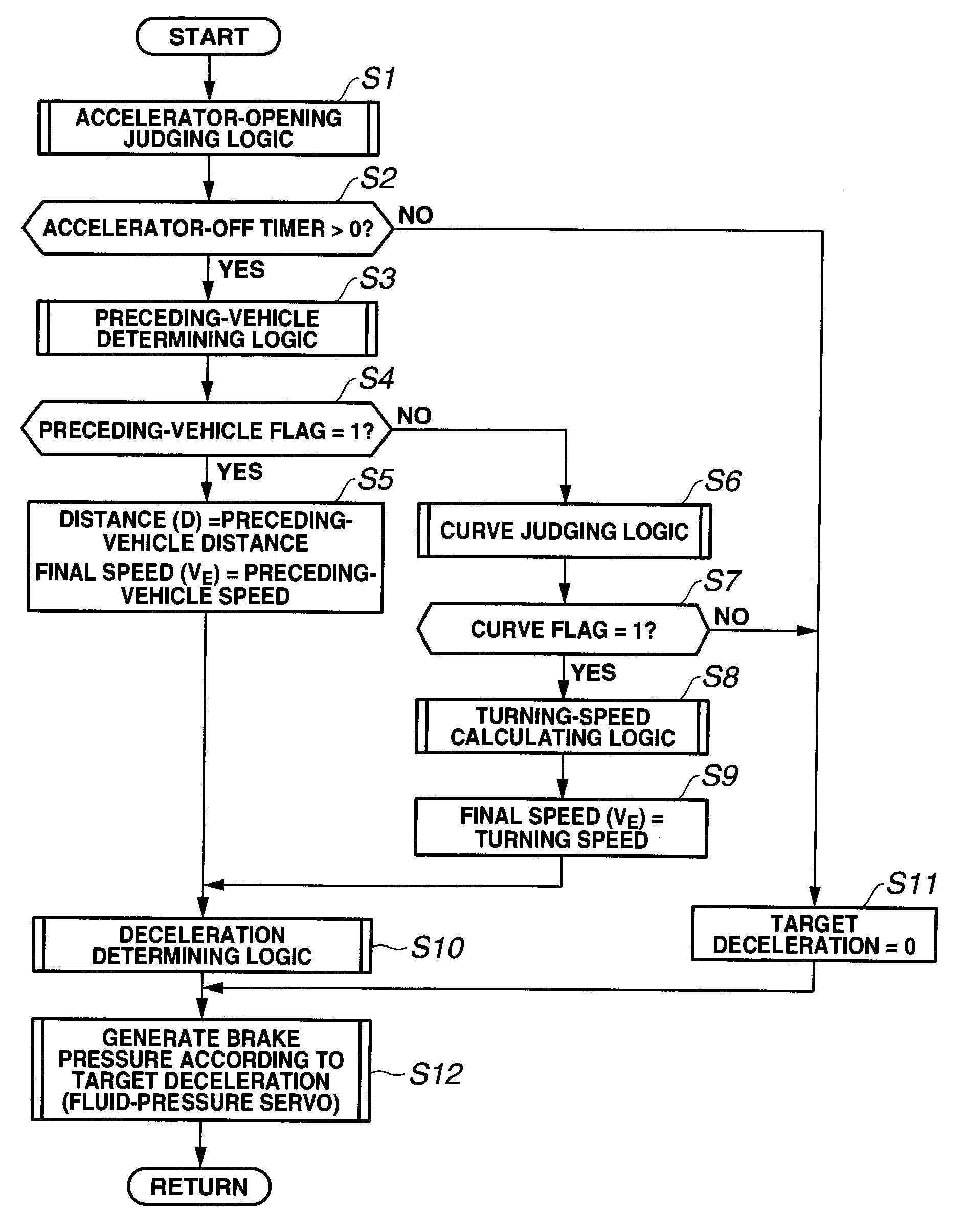
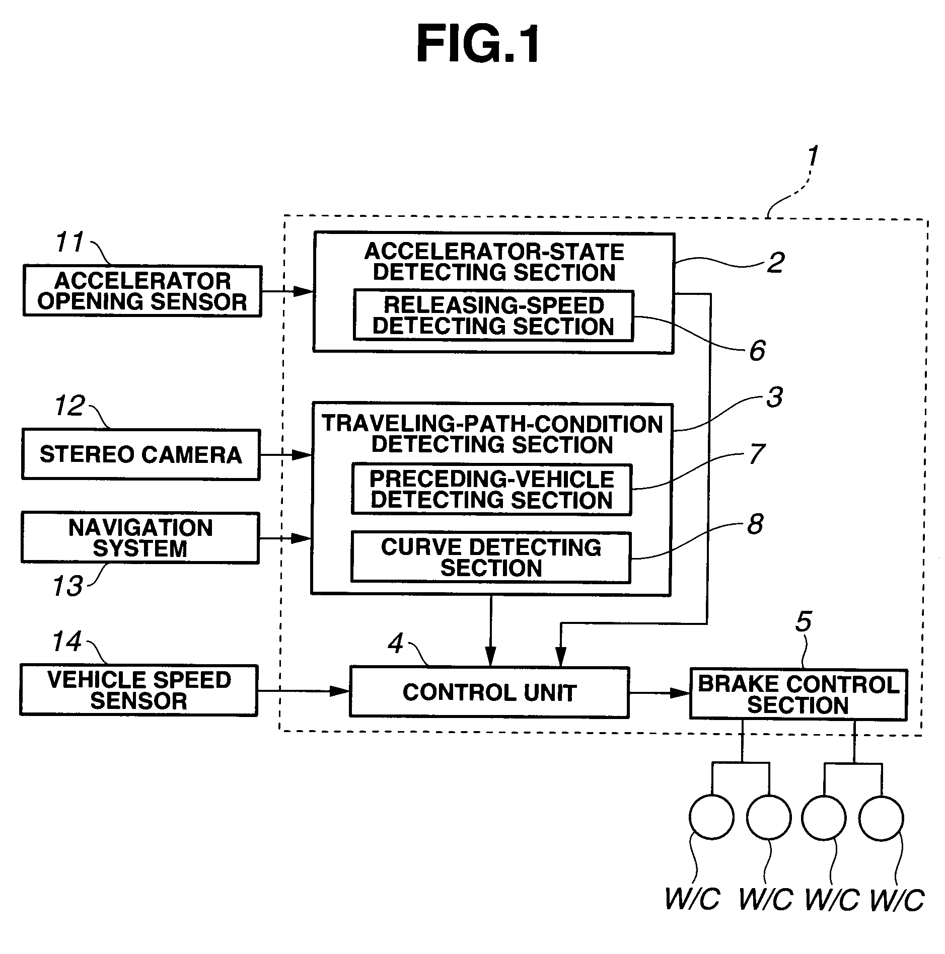
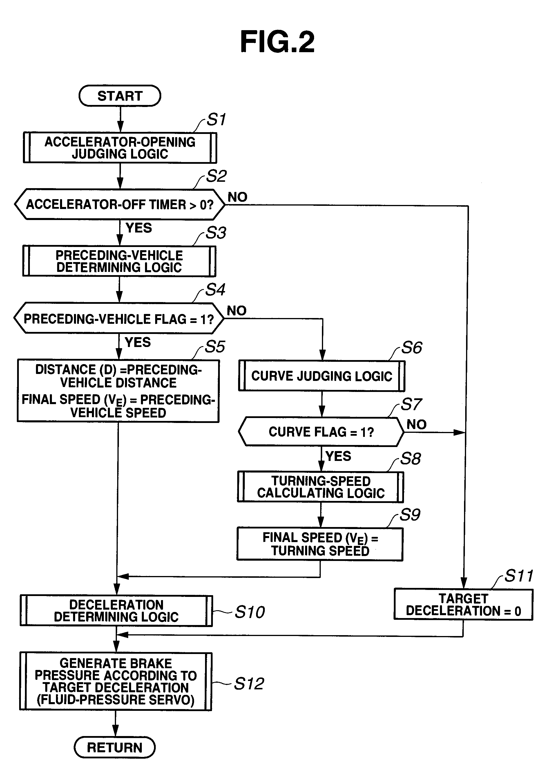
[0028]At first, a system configuration in a first embodiment according the present invention is now explained. FIG. 1 is a schematic system configuration view of a vehicle control apparatus 1 in the first embodiment. The vehicle control apparatus 1 in the first embodiment includes an accelerator-state detecting section 2, a traveling-path-condition detecting section 3, a control unit 4, and a brake control section 5.

[0029]The accelerator-state detecting section 2 detects a manipulating state of accelerator (e.g., on / off of accelerator) according to an intention of driver at the time of running of a host vehicle. The accelerator-state detecting section 2 detects the manipulating state of accelerator on the basis of an accelerator opening which is inputted from an accelerator opening sensor (a speed-up intention detecting section) 11. This accelerator-state detecting section 2 includes an accelerator releasing-speed detecting section 6 functioning to detect a releasing speed of (an ea...


PUM


Abstract

A vehicle control apparatus includes an accelerator-state detecting section configured to detect an accelerator manipulating state of a driver; a traveling-path-condition detecting section configured to detect a condition of a traveling path of a host vehicle; a brake control section configured to cause the host vehicle to automatically generate a braking force; and a control unit configured to control the brake control section on the basis of an input from the accelerator-state detecting section. The control unit is configured to actuate the brake control section in a case where the accelerator-state detecting section detects a decrease of a manipulated variable of the accelerator or an off-state of the accelerator and also where the traveling-path-condition detecting section detects a target object for speed reduction on the traveling path.

Description

BACKGROUND OF THE INVENTION[0001]The present invention relates to a vehicle control apparatus including a brake control section configured to automatically produce braking force.[0002]Japanese Patent Application Publication No. H6-036187 discloses a technique related to an automatic brake. In this technique, a proper turning speed (cornering speed) of a host vehicle at a curve ahead of the host vehicle is calculated based on a map information derived from a navigation system. Moreover, a deceleration required to achieve the proper turning speed is calculated from a current speed of the host vehicle and a distance to the curve. Thereby, the host vehicle is decelerated before the curve if the required deceleration is greater than a predetermined permissible deceleration.SUMMARY OF THE INVENTION[0003]However, in the above technique, a speed-reduction start timing of the automatic brake is determined based on only a vehicle speed for entry to the curve. Hence, a deviation is caused betw...

Claims


Application Information

Patent Timeline
IPC IPC(8): B60T7/12B60T8/172B60W30/00B60W30/09B60W40/08G08G1/16
CPCB60T7/22B60W2750/308B60T2201/16B60T2210/24B60W30/162B60W2420/42B60W2520/10B60W2540/10B60W2540/106B60W2550/10B60W2550/302B60W2550/306B60W2550/402B60W2720/106B60T2201/02B60W2554/4041B60W2754/30B60W2554/804B60W2556/50B60W2554/00B60W2554/4042B60W30/18145
Inventor KUBO, JUNTAKAHASHI, AKIRA
Owner HITACHI LTD
Why Eureka
Try Eureka