Method of folding a sheet of packing material about a group of cigarettes

Inactive Publication Date: 2009-12-31
GD SPA
12 Cites 2 Cited by

AI-Extracted Technical Summary

Problems solved by technology

When the lid only covers a lateral portion of the packet (as described, for example, in U.S. Pat. No. 5,957,280) and the sheet of inner packing material is first folded into a U about the gro...

Benefits of technology

[0008]It is an object of the present invention to provide a method of folding a sheet of packing material about a group of...

Abstract

A method of folding a sheet (2) of packing material about a group (3) of cigarettes; the method includes the steps of: bringing a first end wall (8a) of the group (3) of cigarettes into contact with the flat sheet (2) of packing material, so that the major transverse edges (10) of the group (3) of cigarettes are parallel to the long sides of the sheet (2) of packing material; folding the sheet (2) of packing material into a U about the major transverse edges (10) of the first end wall (8a), so that the sheet (2) of packing material partly covers both the major lateral walls (6) of the group (3) of cigarettes; folding the sheet (2) of packing material about the minor transverse edges (10) of the first end wall (8a), so that the sheet (2) of packing material completely covers both the major lateral walls (6) and the minor lateral walls (7), and forms a tubular package having one open end at a second end wall (8b); and folding the sheet (2) of packing material onto the second end wall (8b) to complete the folding of the sheet (2) of packing material about the group (3) of cigarettes.

Application Domain

Packaging cigaretteWrapper folding/bending apparatus +1

Technology Topic

Image

  • Method of folding a sheet of packing material about a group of cigarettes
  • Method of folding a sheet of packing material about a group of cigarettes
  • Method of folding a sheet of packing material about a group of cigarettes

Examples

  • Experimental program(1)

Example

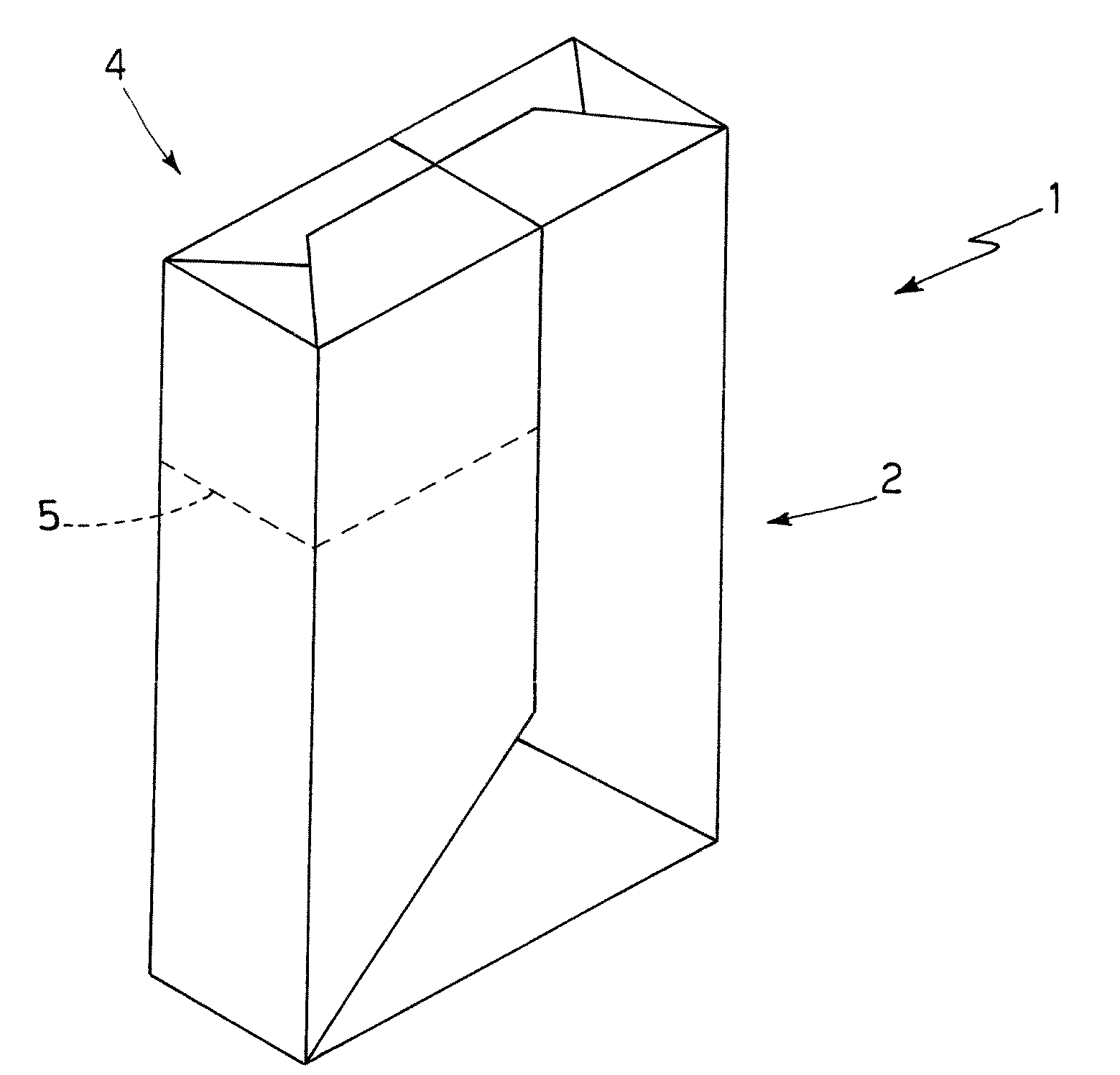
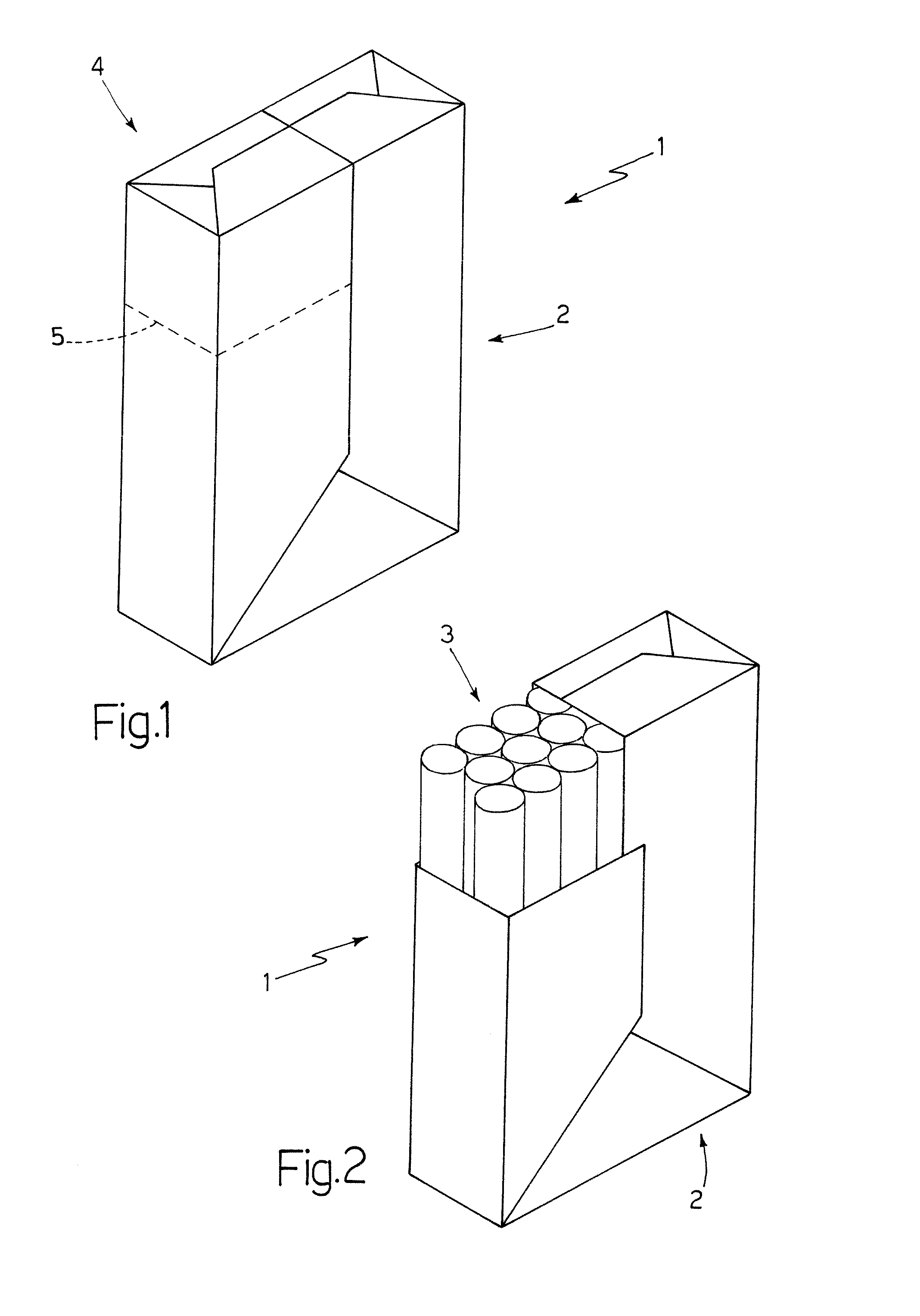
[0023]Number 1 in FIG. 1 indicates as a whole a package defined by a sheet 2 of foil packing material folded about an orderly group 3 of cigarettes (FIG. 2) in the form of a rectangular-section parallelepiped. Package 1 comprises a tear-off top portion 4 defined by a tear-off line 5, and which, when package 1 is first opened, is tom off to permit easy access to group 3 of cigarettes.
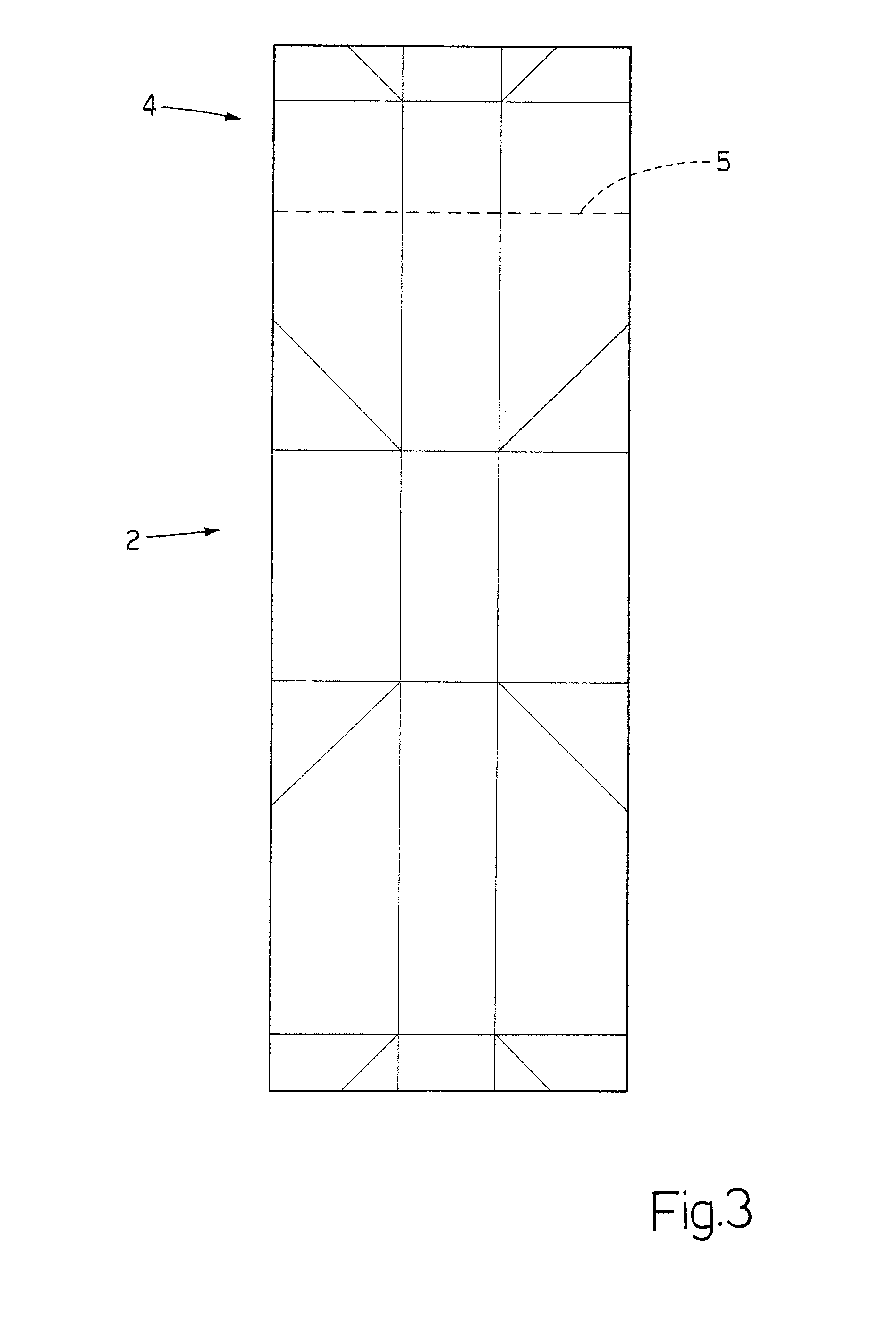
[0024]As shown in FIG. 3, sheet 2 of packing material is in the form of an elongated rectangle, and comprises two parallel opposite long sides, and two parallel opposite short sides.
[0025]As shown in FIG. 4, group 3 of cigarettes is substantially in the form of a rectangular-section parallelepiped, and comprises two parallel, opposite, rectangular major lateral walls 6 (only one shown in FIG. 4) defined by the cylindrical lateral walls of the cigarettes; two parallel, opposite, rectangular minor lateral walls 7 (only one shown in FIG. 4) defined by the cylindrical lateral walls of the cigarettes and smaller than major lateral walls 6; and two parallel, opposite, rectangular end walls 8 (only one shown in FIG. 4) defined by the flat ends of the cigarettes. Four longitudinal edges 9 are defined between the two major lateral walls 6 and the two minor lateral walls 7; four major transverse edges 10 are defined between the two major lateral walls 6 and the two end walls 8; and four minor transverse edges 10 are defined between the two minor lateral walls 7 and the two end walls 8.
[0026]The way in which sheet 2 of packing material is folded about group 3 of cigarettes to form package 1 in FIG. 1 will now be described with particular reference to FIGS. 4-8.
[0027]Firstly, as shown in FIG. 4, a first end wall 8a of group 3 of cigarettes is brought into contact with the flat sheet 2 of packing material, so that major transverse edges 10 of group 3 of cigarettes are parallel to the long sides of sheet 2 of packing material, and minor transverse edges 10 of group 3 of cigarettes are parallel to the short sides of sheet 2 of packing material. First end wall 8a of group 3 of cigarettes is preferably positioned symmetrically in the centre of sheet 2 of packing material with respect to both the long sides and short sides of sheet 2 of packing material.
[0028]Next, as shown in FIG. 5, sheet 2 of packing material is folded into a U about the major transverse edges 10 of first end wall 8a, so that sheet 2 of packing material partly covers both the major lateral walls 6.
[0029]At this point, as shown in FIGS. 6 and 7, sheet 2 of packing material is folded about the minor transverse edges 10 of first end wall 8a, so that sheet 2 of packing material covers the whole of both major lateral walls 6 and minor lateral walls 7, and forms a tubular package having one open end at a second end wall 8b opposite first end wall 8a. It is important to note that, at this stage, sheet 2 of packing material forms two Z-shaped folds, which locally impart a triangular shape to sheet 2 of packing material, are partly superimposed, and are located close to first end wall 8a.
[0030]Finally, as shown in FIG. 8, sheet 2 of packing material is folded onto second end wall 8b to complete the folding of sheet 2 of packing material about group 3 of cigarettes and so form package 1. More specifically, the step of folding sheet 2 of packing material onto second end wall 8b comprises folding sheet 2 of packing material about the two minor transverse edges 10 of second end wall 8b (FIG. 8), and then folding sheet 2 of packing material about the two major transverse edges 10 of second end wall 8b.
[0031]As shown in the attached drawings, sheet 2 of packing material has only one tear-off line 5, which is parallel and close to a short side of sheet 2 of packing material, and defines tear-off top portion 4. Consequently, tear-off top portion 4 only applies to part of the top end of package 1, as shown clearly in FIGS. 1 and 2. This embodiment is particularly suitable for a rigid packet with a hinged lid covering only a lateral portion of the rigid packet (as described, for example, in U.S. Pat. No. 5,957,280).
[0032]In a different embodiment, not shown, sheet 2 of packing material has two tear-off lines 5, each parallel and close to a short side of sheet 2 of packing material and defining tear-off top portion 4, which therefore applies to the whole top end of package 1. This embodiment is particularly suitable for a rigid packet with a hinged lid covering a whole top portion of the rigid packet. In another embodiment, not shown, sheet 2 of packing material has two tear-off lines 5, each of which is parallel and close to a short side of sheet 2 of packing material, is shorter than the short side of sheet 2 of packing material, and defines tear-off top portion 4.
[0033]Number 1 in FIG. 9 indicates as a whole a package defined by a sheet 2 of foil packing material folded about an orderly group 3 of cigarettes (FIG. 10) in the form of a parallelepiped with an equilateral triangular cross section. Package 1 comprises a tear-off top portion 4 defined by a tear-off line 5, and which, when package 1 is first opened, is torn off to permit easy access to group 3 of cigarettes.
[0034]As shown in FIG. 11, sheet 2 of packing material is in the form of an elongated rectangle, and comprises two parallel opposite long sides, and two parallel opposite short sides.
[0035]As shown in FIG. 12, group 3 of cigarettes is substantially parallelepiped-shaped with a triangular cross section, and comprises three rectangular lateral walls 11 (only two shown in FIG. 12) defined by the cylindrical lateral walls of the cigarettes; and two parallel, opposite, triangular end walls 8 (only one shown in FIG. 12) defined by the flat ends of the cigarettes. Three longitudinal edges 9 are defined between lateral walls 11; and six transverse edges 10 are defined between lateral walls 11 and the two end walls 8.
[0036]The way in which sheet 2 of packing material is folded about group 3 of cigarettes to form package 1 in FIG. 9 will now be described with particular reference to FIGS. 12-15.
[0037]Firstly, as shown in FIG. 12, a first end wall 8a of group 3 of cigarettes is brought into contact with the flat sheet 2 of packing material, so that a first lateral wall 11a of group 3 of cigarettes is perpendicular to the long sides of sheet 2 of packing material and parallel to the short sides of sheet 2 of packing material, and, consequently, a second lateral wall 11b and a third lateral wall 11c of group 3 of cigarettes slope with respect to the long sides and short sides of sheet 2 of packing material. First end wall 8a of group 3 of cigarettes is preferably positioned symmetrically in the centre of sheet 2 of packing material with respect to both the long sides and short sides of sheet 2 of packing material.
[0038]Next, as shown in FIG. 13, a first portion of sheet 2 of packing material is folded onto first lateral wall 11a.
[0039]At this point, as shown in FIG. 14, the ends of the first portion of sheet 2 of packing material projecting from first lateral wall 11a are folded onto second lateral wall 11b and third lateral wall 11c; and, as shown in FIG. 14, a second portion of sheet 2 of packing material, opposite the first portion, is then folded onto second lateral wall 11b and third lateral wall 11c, and partly onto the previously folded first portion of sheet 2 of packing material to form a tubular package having one open end at a second end wall 8b.
[0040]Finally, as shown in FIG. 15, sheet 2 of packing material is folded onto second end wall 8b to complete the folding of sheet 2 of packing material about group 3 of cigarettes and so form package 1. More specifically, the step of folding sheet 2 of packing material onto second end wall 8b comprises folding sheet 2 of packing material successively about the three transverse edges 10 of second end wall 8b.
[0041]As shown in the attached drawings, sheet 2 of packing material has two tear-off lines 5, each parallel and close to a short side of sheet 2 of packing material and defining tear-off top portion 4, which therefore applies to the whole top end of package 1, as shown clearly in FIGS. 9 and 10. This embodiment is particularly suitable for a rigid packet with a hinged lid covering a whole top portion of the rigid packet. In another embodiment, not shown, sheet 2 of packing material has two tear-off lines 5, each of which is parallel and close to a short side of sheet 2 of packing material, is shorter than the short side of sheet 2 of packing material, and defines tear-off top portion 4.
[0042]In a different embodiment, not shown, sheet 2 of packing material has only one tear-off line 5, which is parallel and close to a short side of sheet 2 of packing material, and defines tear-off top portion 4. Consequently, tear-off top portion 4 only applies to part of the top end of package 1. This embodiment is particularly suitable for a rigid packet with a hinged lid covering only a lateral portion of the rigid packet (as described, for example, in U.S. Pat. No. 5,957,280).
[0043]Number 1 in FIG. 22 indicates as a whole a package defined by a sheet 2 of foil packing material folded about an orderly group 3 of cigarettes (FIG. 16) in the form of a parallelepiped with a non-equilateral octagonal cross section (i.e. in which not all the sides of the octagon are equal). Package 1 comprises a tear-off top portion 4 defined by a tear-off line 5, and which, when package 1 is first opened, is torn off to permit easy access to group 3 of cigarettes.
[0044]As shown in FIG. 16, sheet 2 of packing material is in the form of an elongated rectangle, and comprises two parallel opposite long sides, and two parallel opposite short sides.
[0045]As shown in FIG. 16, group 3 of cigarettes is substantially in the form of an octagonal-section parallelepiped, and comprises eight rectangular lateral walls 11 (only three shown in FIG. 16) defined by the cylindrical lateral walls of the cigarettes; and two parallel, opposite, octagonal end walls 8 (only one shown in FIG. 16) defined by the flat ends of the cigarettes. Eight longitudinal edges are defined between the eight lateral walls 11; and sixteen transverse edges are defined between the eight lateral walls 11 and the two end walls 8.
[0046]The way in which sheet 2 of packing material is folded about group 3 of cigarettes to form package 1 in FIG. 22 will now be described with particular reference to FIGS. 16-21.
[0047]Firstly, as shown in FIG. 16, a first end wall 8a of group 3 of cigarettes is brought into contact with the flat sheet 2 of packing material, and is preferably positioned symmetrically in the centre of sheet 2 of packing material with respect to both the long sides and short sides of sheet 2 of packing material.
[0048]Next, as shown in FIG. 17, sheet 2 of packing material is folded into a U about group 3 of cigarettes by folding two opposite portions of sheet 2 of packing material onto two parallel opposite first lateral walls 11a of group 3 of cigarettes.
[0049]At this point, as shown in FIG. 18, the ends of sheet 2 of packing material projecting from first end wall 8a of group 3 of cigarettes are folded onto two parallel opposite second lateral walls 11b, perpendicular to first lateral walls 11a, of group 3 of cigarettes.
[0050]As shown in FIGS. 19 and 20, the four flaps of sheet 2 of packing material projecting from first lateral walls 11a of group 3 of cigarettes are folded in twos one on top of the other and onto second lateral walls 11b of group 3 of cigarettes to form a tubular package having one open end at a second end wall 8b.
[0051]Finally, as shown in FIG. 21, sheet 2 of packing material is folded onto second end wall 8b to complete the folding of sheet 2 of packing material about group 3 of cigarettes and so form package 1. More specifically, the step of folding sheet 2 of packing material onto second end wall 8b comprises folding sheet 2 of packing material successively about four transverse edges of second end wall 8b.
[0052]Number 1 in FIG. 29 indicates as a whole a package defined by a sheet 2 of foil packing material folded about an orderly group 3 of cigarettes (FIG. 23) in the form of a parallelepiped with an isosceles trapezoidal cross section. Package 1 comprises a tear-off top portion 4 defined by a tear-off line 5, and which, when package 1 is first opened, is torn off to permit easy access to group 3 of cigarettes.
[0053]As shown in FIG. 23, sheet 2 of packing material is in the form of an elongated rectangle, and comprises two parallel opposite long sides, and two parallel opposite short sides.
[0054]As shown in FIG. 23, group 3 of cigarettes is substantially in the form of a parallelepiped with an isosceles trapezoidal cross section, and comprises four rectangular lateral walls 11 (only two shown in FIG. 23) defined by the cylindrical lateral walls of the cigarettes; and two parallel, opposite, trapezoidal end walls 8 (only one shown in FIG. 23) defined by the flat ends of the cigarettes. Four longitudinal edges are defined between the four lateral walls 11; and eight transverse edges are defined between the four lateral walls 11 and the two end walls 8. More specifically, two lateral walls 11a are parallel opposite major lateral walls, and two lateral walls 11b are minor lateral walls sloping towards each other and smaller than major lateral walls 11a.
[0055]The way in which sheet 2 of packing material is folded about group 3 of cigarettes to form package 1 in FIG. 29 will now be described with particular reference to FIGS. 23-28.
[0056]Firstly, as shown in FIG. 23, a first end wall 8a of group 3 of cigarettes is brought into contact with the flat sheet 2 of packing material, and is preferably positioned symmetrically in the centre of sheet 2 of packing material with respect to both the long sides and short sides of sheet 2 of packing material.
[0057]Next, as shown in FIG. 24, sheet 2 of packing material is folded into a U about group 3 of cigarettes by folding two opposite portions of sheet 2 of packing material onto two parallel opposite first lateral walls 11a of group 3 of cigarettes.
[0058]At this point, as shown in FIG. 25, the ends of sheet 2 of packing material projecting from first end wall 8a of group 3 of cigarettes are folded onto two opposite second lateral walls 11b, sloping with respect to first lateral walls 11a, of group 3 of cigarettes.
[0059]As shown in FIGS. 26 and 27, the four flaps of sheet 2 of packing material projecting from first lateral walls 11a of group 3 of cigarettes are folded in twos one on top of the other and onto second lateral walls 11b of group 3 of cigarettes to form a tubular package having one open end at a second end wall 8b.
[0060]Finally, as shown in FIG. 28, sheet 2 of packing material is folded onto second end wall 8b to complete the folding of sheet 2 of packing material about group 3 of cigarettes and so form package 1. More specifically, the step of folding sheet 2 of packing material onto second end wall 8b comprises folding sheet 2 of packing material successively about the four transverse edges of second end wall 8b.
[0061]The method of folding sheet 2 of packing material about group 3 of cigarettes has several advantages: it is cheap and easy to implement on a packing machine and, above all, provides for straight tear-off lines 5, in the case of both a rigid packet with a hinged lid covering only a lateral portion of the rigid packet (FIGS. 1 and 2), and a rigid packet with a hinged lid covering the whole top portion of the rigid packet (FIGS. 9 and 10).

PUM

no PUM

Description & Claims & Application Information

We can also present the details of the Description, Claims and Application information to help users get a comprehensive understanding of the technical details of the patent, such as background art, summary of invention, brief description of drawings, description of embodiments, and other original content. On the other hand, users can also determine the specific scope of protection of the technology through the list of claims; as well as understand the changes in the life cycle of the technology with the presentation of the patent timeline. Login to view more.

Similar technology patents

Appliance for distributing a precut wiping material that is rolled up or folded in a Z shape

InactiveUS9408505B2Cheap to implementEffective interventionFilament handlingDomestic applicationsSkin flapCam
Owner:GRANGER MAURICE

Classification and recommendation of technical efficacy words

  • Cheap to implement

Method of raising a building

Owner:SO L E S SOC LAVORI EDILI E SERBATOI +1

Method of controlling an automatic production/packing machine

InactiveUS20090044491A1Cheap to implementCapsCapping machinery safety/controlManufacturing engineeringControl unit
Owner:GD SPA

Cigarette packing machine for producing rigid hinged-lid packets

InactiveUS20060254212A1Cheap to implementPackaging cigaretteWrapper folding/bending apparatusCigarette packEngineering
Owner:GD SPA
Why Eureka
Try Eureka