
UV generated visible light source

a visible light source and uv technology, applied in the direction of instruments, discharge tubes, luminescnet screens, etc., can solve the problems of relatively short life expectancy of bulbs or diodes, relatively high power requirements, and several limitations of approaches, so as to achieve cost-effective and reliable production of visible light

Inactive Publication Date: 2009-12-31
CARDULLO MARIO W
View PDF17 Cites 4 Cited by
  • Summary
  • Abstract
  • Description
  • Claims
  • Application Information

AI Technical Summary

Benefits of technology

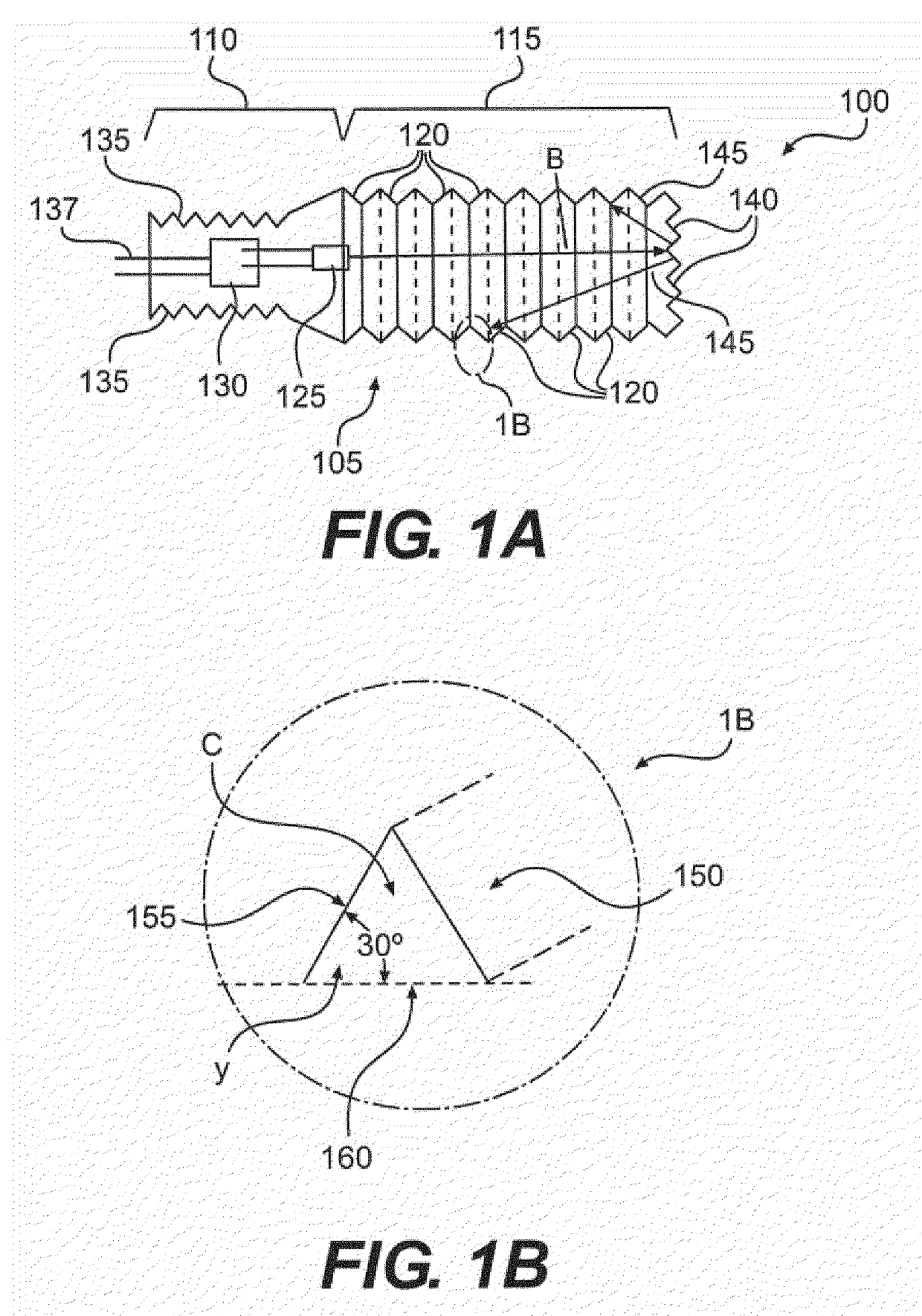
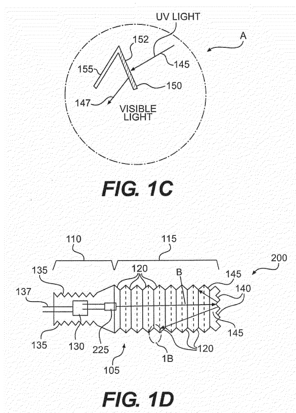
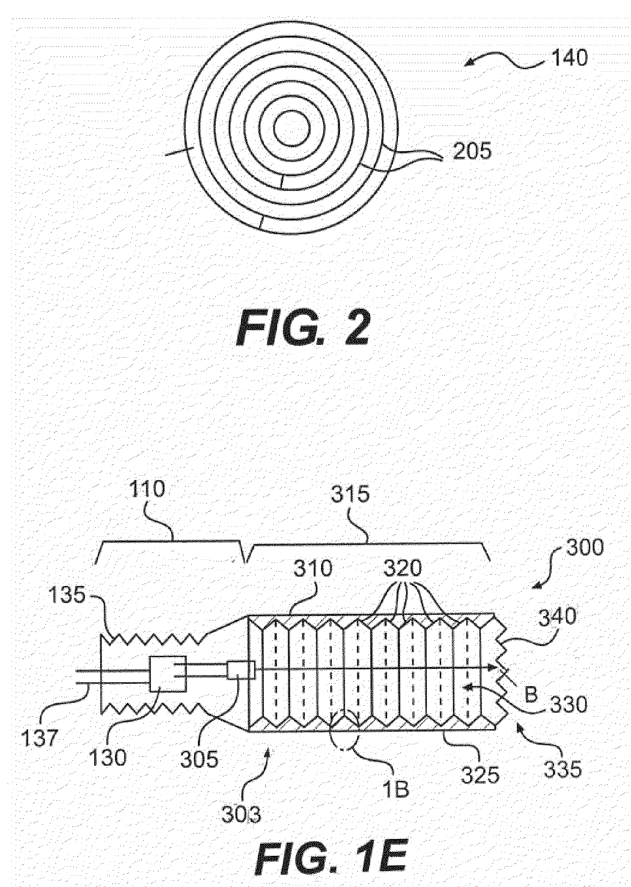
[0009]The invention meets the foregoing need and includes a method and apparatus to cost effectively and reliably produce visible light from a UV light source. In one aspect, the invention includes producing visible light by generally directing UV light onto a UV light reactive surface to produce visible light. This surface may comprise a reflective surface.

Problems solved by technology

These approaches have several limitations.
For example, the power requirement may be relatively high and the bulbs or diodes may have a relatively short life expectation due to being damaged in normal use, or by burn-out.
Furthermore, some may have complicated structures and use dangerous chemicals such as compact fluorescents.
Moreover, the amount of lumens produced may be relatively limited.
Yet, incandescent lighting is highly inefficient compared to fluorescent light: in an incandescent bulb, fully 90% of the energy output is wasted on heat, which comes through the infrared region.

Method used


Image

  • UV generated visible light source
  • UV generated visible light source
  • UV generated visible light source

Examples


Embodiment Construction

[0021]It is understood that the invention is not limited to the particular methodology, protocols, etc., described herein, as these may vary as the skilled artisan will recognize. It is also to be understood that the terminology used herein is used for the purpose of describing particular embodiments only, and is not intended to limit the scope of the invention. It is also to be noted that as used herein and in the appended claims, the singular forms “a,”“an,” and “the” include the plural reference unless the context clearly dictates otherwise. Thus, for example, a reference to “an address” is a reference to one or more addresses and equivalents thereof known to those skilled in the art.

[0022]Unless defined otherwise, all technical and scientific terms used herein have the same meanings as commonly understood by one of ordinary skill in the art to which the invention pertains. The embodiments of the invention and the various features and advantageous details thereof are explained mo...


PUM


Abstract

A device and method for an ultraviolet light (UV) light based visible light generator is disclosed. The UV light source emits a beam of UV light that may be scattered onto surfaces including UV light reactive materials that produces visible light when excited by the scattered UV light. The UV light may be coherent or non-coherent light.

Description

CROSS-REFERENCE TO RELATED APPLICATIONS[0001]This application claims benefit and priority to U.S. Provisional Application No. 61 / 075,398 filed Jun. 25, 2008 entitled UV-LASER GENERATED VISIBLE LIGHT SOURCE, and also to U.S. Provisional Application No. 61 / 079,206 filed Jul. 9, 2008 entitled UV-LASER GENERATED VISIBLE LIGHT SOURCE, the disclosures of which are incorporated by reference herein in their entirety.BACKGROUND OF THE INVENTION[0002]1. Field of the Invention[0003]The invention is directed to an apparatus and method for generating visible light and, more particularly, to an apparatus and method for generating visible light using an ultraviolet laser, or similar UV light source.[0004]2. Related Art[0005]Light generating sources today, such as flashlights or general light bulbs, for example, use traditional techniques for generating light that might involve an incandescent bulb or in newer versions, compact fluorescents, light emitting diodes (LEDs) and the like. These approach...

Claims


Application Information

Patent Timeline
Patent Type & Authority Applications(United States)
IPC IPC(8): H01J1/62
CPCB82Y20/00G02B6/001H01S5/34333F21K9/56G02B6/0096G02B6/0003G02B6/0016G02B6/0073G02B6/0001H01S5/32341H01S5/0087
Inventor CARDULLO, MARIO W.
Owner CARDULLO MARIO W
Learn More