Drop volume compensation for ink supply variation

a drop volume compensation and ink supply technology, applied in the field of drop volume compensation for ink supply variation, can solve the problems of objectionable image differences, sources etc., and achieve the effect of reducing the amount of variation in the size of ejecting ink drop, reducing the amount of drop volume variation, and maintaining image quality

Inactive Publication Date: 2009-12-31
EASTMAN KODAK CO
View PDF11 Cites 10 Cited by
  • Summary
  • Abstract
  • Description
  • Claims
  • Application Information

AI Technical Summary

Benefits of technology

[0007]Accordingly, an object of the present invention is to maintain image quality by reducing unintended variations in drop volume through the adjustment of ink drop ejecting conditions depending on the amount of ink remaining in an ink tank chamber, and/or the ink demand for printing an image.
[0008]The present invention therefore relates to a method of p...

Problems solved by technology

If there is excessive variability of the drop volume from one printed image to another, the appearance diffe...

Method used


Image

  • Drop volume compensation for ink supply variation
  • Drop volume compensation for ink supply variation
  • Drop volume compensation for ink supply variation

Examples


Embodiment Construction

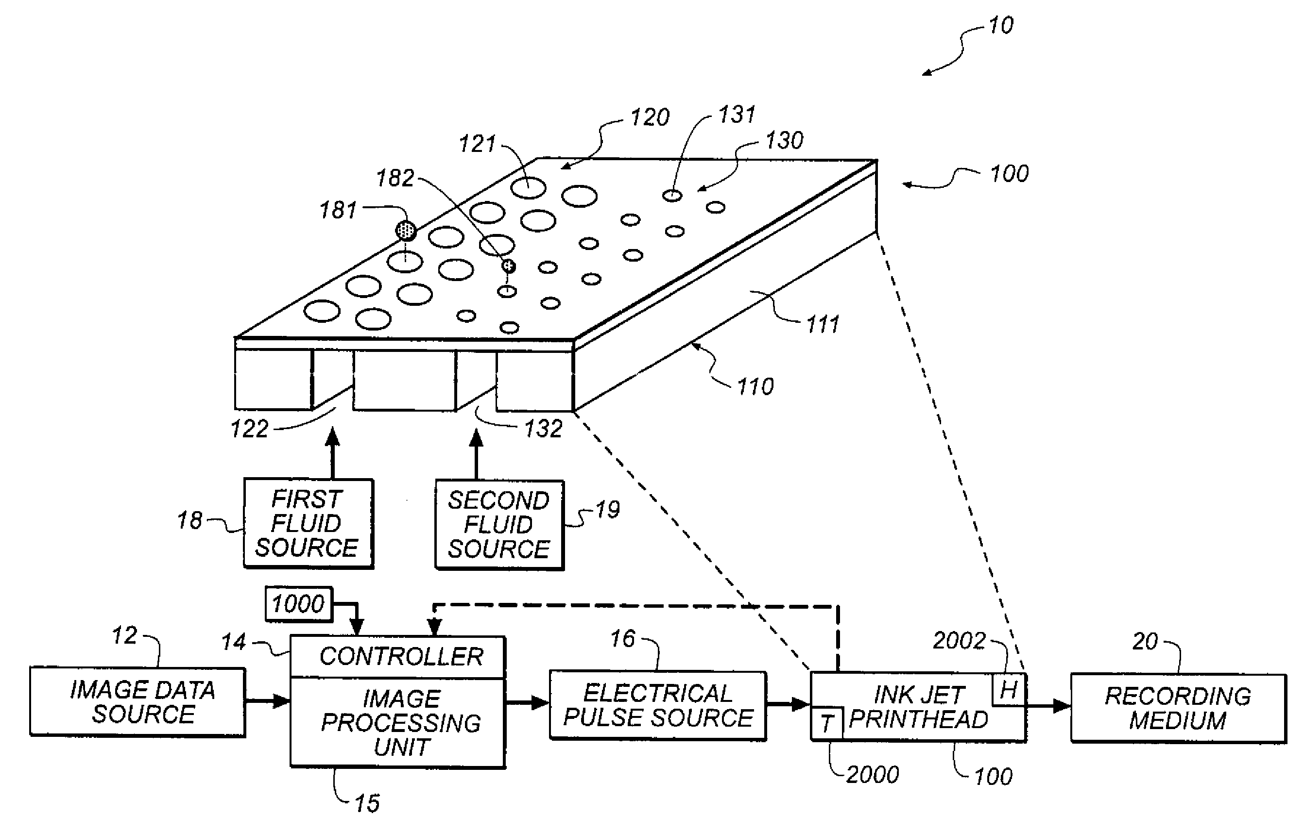
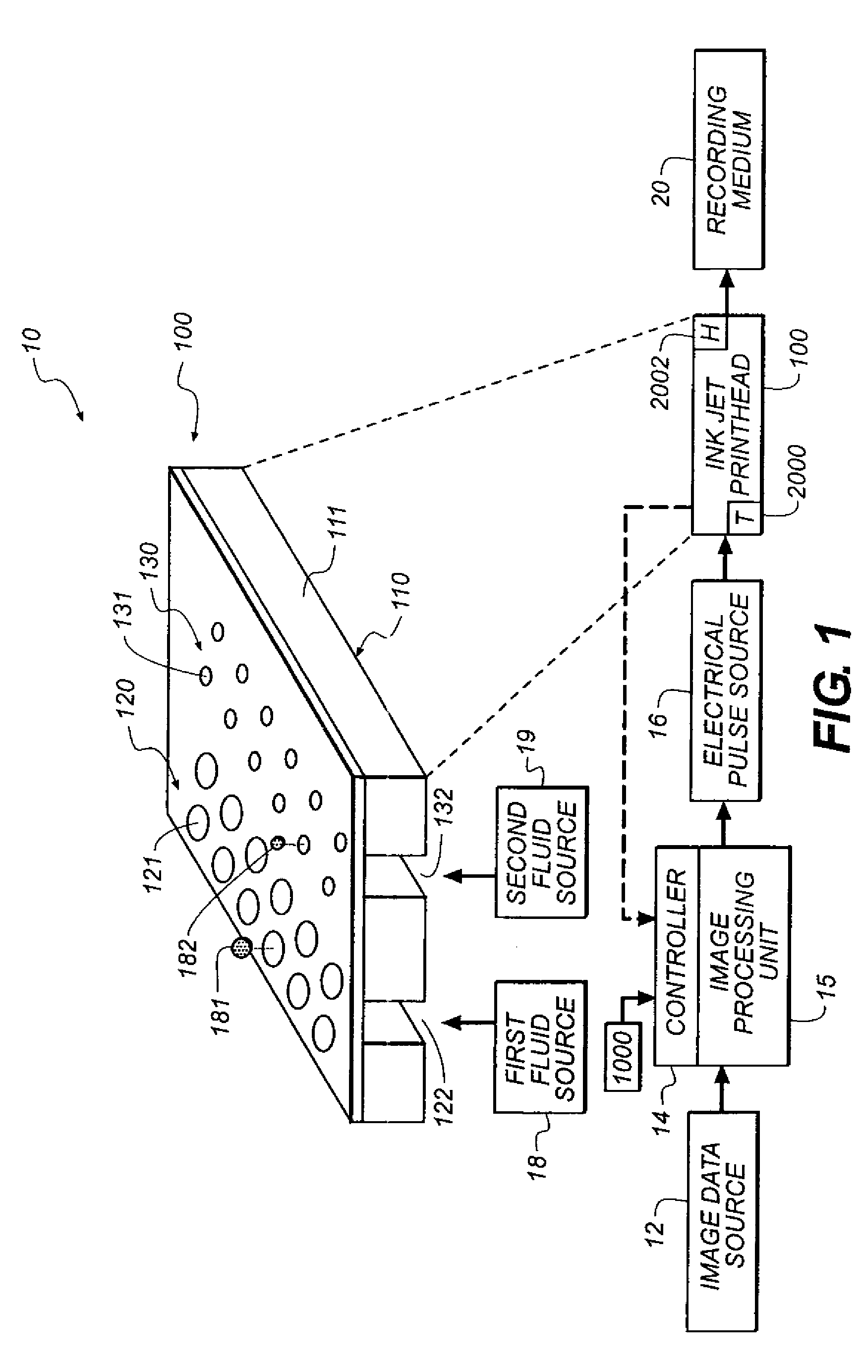
[0020]Referring to FIG. 1, a schematic representation of an inkjet printer system 10 is shown, as described in U.S. Pat. No. 7,350,902. The system includes a source 12 of image data which provides signals that are interpreted by a controller 14 as being commands to eject drops. Controller 14 includes an image processing unit 15 for rendering images for printing, and outputs signals to a source 16 of electrical energy pulses that are inputted to the inkjet printhead 100 which includes at least one printhead die 110. In the example shown in FIG. 1, there are two nozzle arrays. Nozzles 121 in the first nozzle array 120 have a larger opening area than nozzles 131 in the second nozzle array 130. In this example, each of the two nozzle arrays has two staggered rows of nozzles, each row having a nozzle density of 600 per inch. The effective nozzle density then in each array is 1200 per inch. If pixels on the recording medium were sequentially numbered along the paper advance direction, the...


PUM


Abstract

The present invention relates to a method that enables image quality of a printed image to be maintained by reducing unintended variations in drop volume, through the adjustment of ink drop ejecting conditions depending on the amount of ink remaining in an ink tank chamber or reservoir, and/or the ink demand for printing an image. The method of printing of the present invention comprises: providing a printhead in fluid communication with an ink chamber or reservoir; detecting at least one parameter related to an amount of negative pressure provided to the printhead; and adjusting an ink drop ejecting condition of the printhead as a function of the parameter so that an amount of variation in size of ejected ink drop is reduced.

Description

CROSS REFERENCE TO RELATED APPLICATIONS[0001]Reference is made to commonly-assigned, U.S. patent application Ser. No. (D. 92457) filed entitled METHOD OF PRINTING FOR INCREASED INK EFFICIENCY in the name of Frederick Donahue et al. incorporated herein by reference.FIELD OF THE INVENTION[0002]The present invention relates generally to the field of inkjet printing, and in particular to a method of printing that provides improved control of drop volume relative to changes in ink supply level and ink demand.BACKGROUND OF THE INVENTION[0003]Inkjet printing systems include a printhead having an array of drop ejectors that are controlled to eject ink in an imagewise fashion on a printing medium. The quality of the image is determined by factors including tone density uniformity and color rendition that depend somewhat on the volume of the drops of ink that are ejected. If there is excessive variability of the drop volume from one printed image to another, the appearance differences between...

Claims


Application Information

Patent Timeline
IPC IPC(8): B41J29/38
CPCB41J2/04535B41J2/0456B41J2/0458B41J2/17556B41J2/17513B41J2/1752B41J2/17523B41J2/04588
Inventor KNEEZEL, GARY A.TRAFTON, R. WINFIELDDONAHUE, FREDERICK A.
Owner EASTMAN KODAK CO
Why Eureka
Try Eureka