
Method and System for Remote Visualization Client Acceleration

a remote visualization and client technology, applied in the field of remote visualization, can solve the problems of network latency and bandwidth, restricting the application of remote visualization,

Inactive Publication Date: 2010-01-07
IBM CORP
View PDF16 Cites 38 Cited by
  • Summary
  • Abstract
  • Description
  • Claims
  • Application Information

AI Technical Summary

Benefits of technology

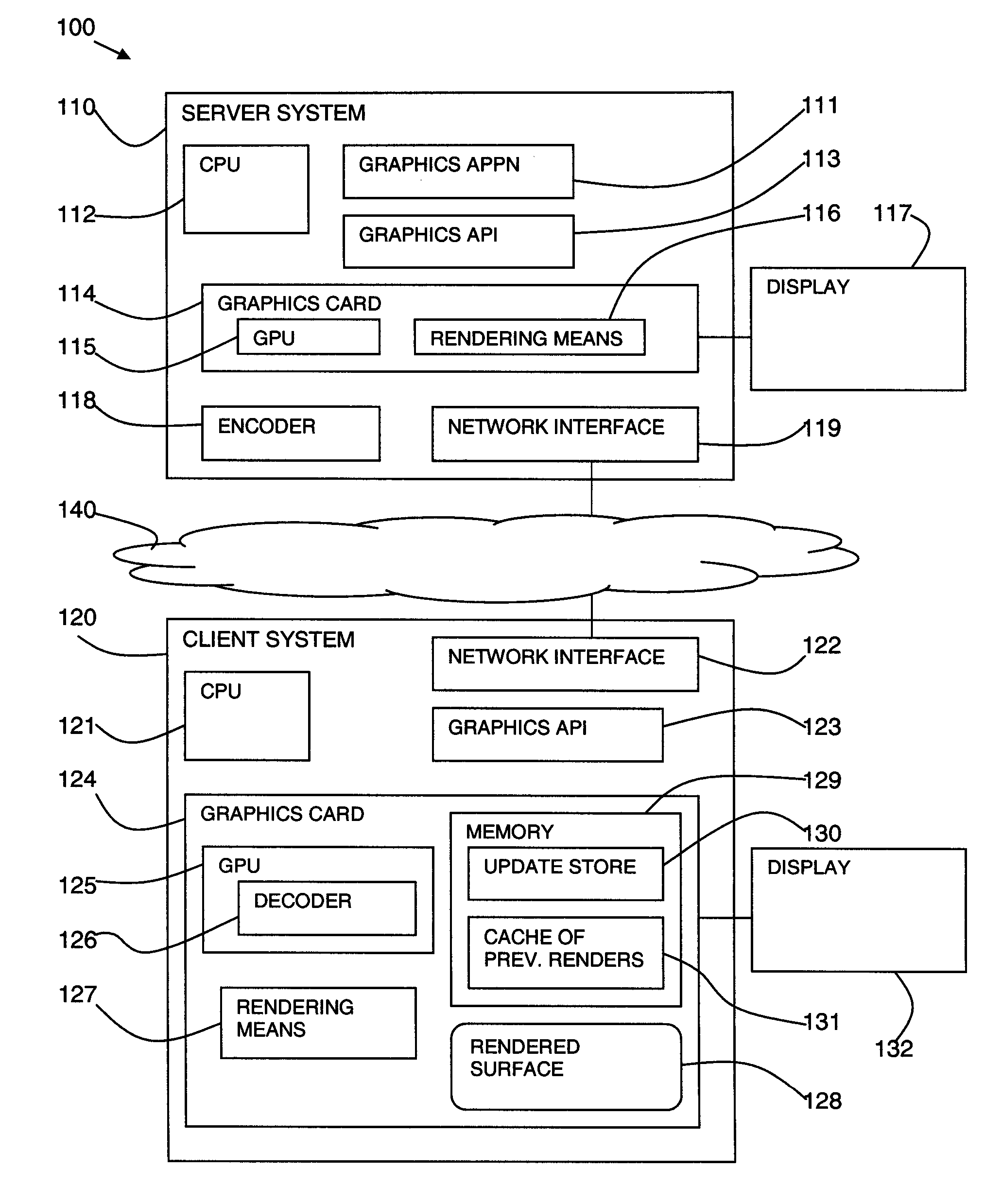
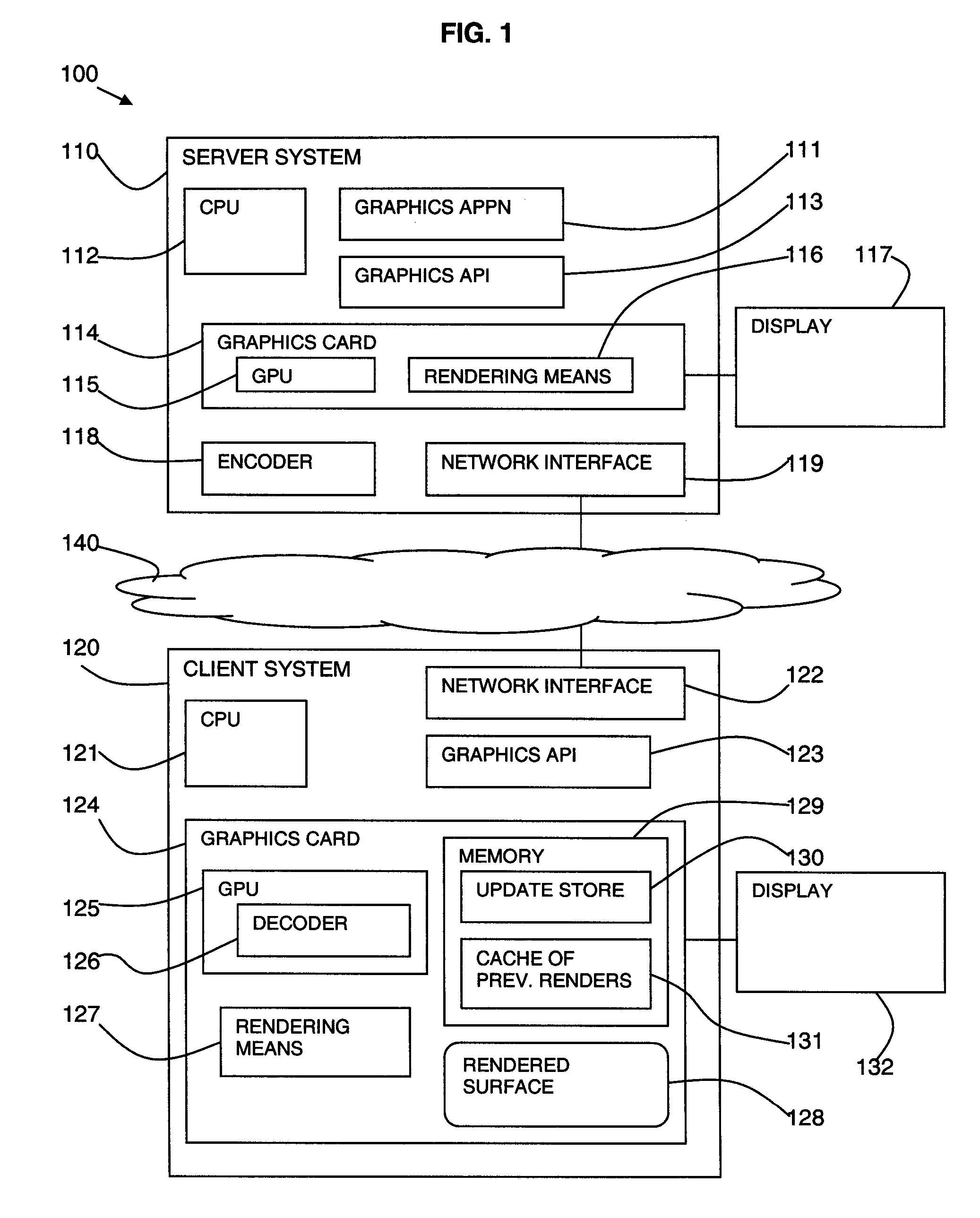
[0012]The invention applies an approach to remote visualization where use of graphics APIs and modern graphics cards' capabilities are combined to optimize costly image decompression at the remote client. This is achieved by off-loading decompression tasks to the graphic hardware GPU and then rendering the full remote desktop image inside a window rendered by the 3D graphic API. The invention applies to the full desktop including 2D and 3D parts and allows different compression schemes to be used.

Problems solved by technology

These applications use graphics APIs (application programming interfaces) for 3D rendering and, due to the complexity of the rendered objects, require special hardware inside the graphics cards to accelerate 3D data processing.
The main restriction to remote visualization applications is network latency and bandwidth.

Method used


Image

  • Method and System for Remote Visualization Client Acceleration
  • Method and System for Remote Visualization Client Acceleration
  • Method and System for Remote Visualization Client Acceleration

Examples


Embodiment Construction

[0018]For a better understanding of the present invention, together with other and further features and advantages thereof, reference is made to the following description, taken in conjunction with the accompanying drawings, and the scope of the invention will be pointed out in the appended claims.

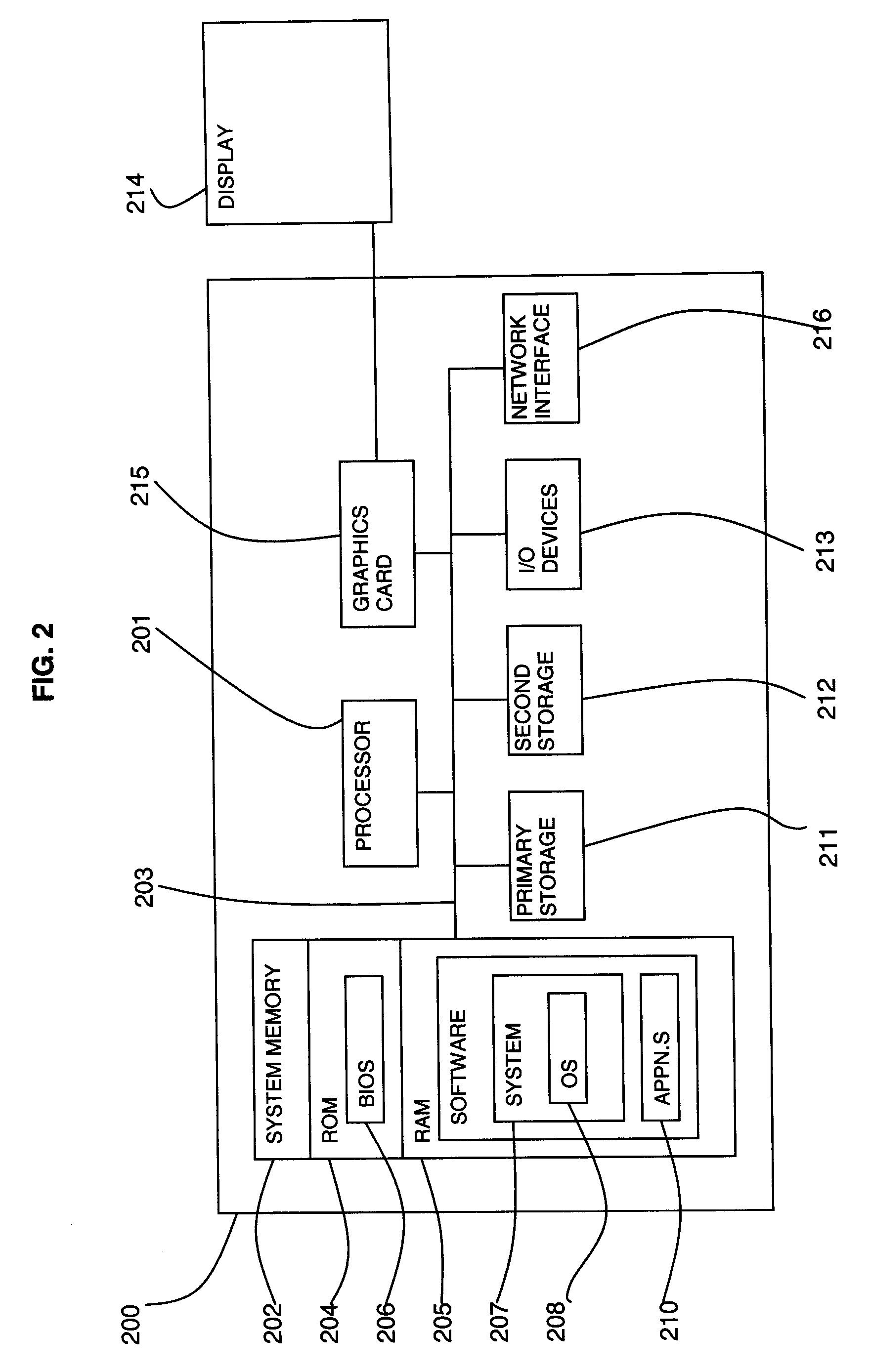
[0019]It will be readily understood that the components of the present invention, as generally described and illustrated in the Figures herein, may be arranged and designed in a wide variety of different configurations. Thus, the following more detailed description of the embodiments of the apparatus, system, and method of the present invention, as represented in FIGS. 1 through 3, is not intended to limit the scope of the invention, as claimed, but is merely representative of selected embodiments of the invention.

[0020]Reference throughout this specification to “one embodiment” or “an embodiment” (or the like) means that a particular feature, structure, or characteristic described in conn...


PUM


Abstract

A method, system, and program product is disclosed for remote visualization in which a server window contents is displayed remotely at a client. The client creates a 3D rendering surface on a client graphics card to display a server window contents and receives update data from the server relating to the server window contents. The update data is uploaded to the client graphics card and the graphics processing unit (GPU) is used to decode the update data and render the update data to the 3D rendering surface. The graphical processing unit includes general purpose computing on graphics processing unit functionality to provide the decoding processing.

Description

FIELD OF THE INVENTION [0001]This invention relates to the field of remote visualization. In particular, it relates to remote visualization client acceleration.BACKGROUND OF THE INVENTION [0002]Remote visualization solutions allow the users of a graphical desktop to interact with graphical applications from a remote machine or thin client.[0003]Thin client viewers receive images over the network, which are rendered to give the end user the impression that they are using an application locally on their computer or workstation. Various implementations and algorithms are used in remote visualization applications and they normally employ image compression and they usually send only the parts of the screen that recently changed in order to optimize the bandwidth available in the network.[0004]Remote applications such as the Open Source VNC (Virtual Network Computing) or Microsoft Remote Desktop (Microsoft is a trade mark of Microsoft Corporation in the US. and other countries) have recen...

Claims


Application Information

Patent Timeline
Patent Type & Authority Applications(United States)
IPC IPC(8): G06T15/00
CPCG06T15/005G06F3/1454G09G2340/02
Inventor HAMILL, JOHNLEVINS, MARKPASETTO, DAVIDE
Owner IBM CORP
Learn More