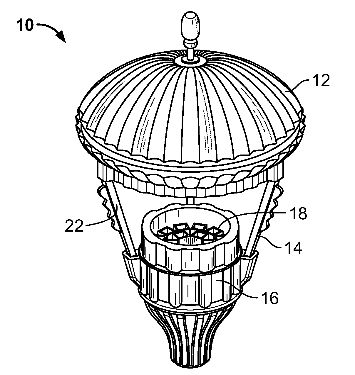
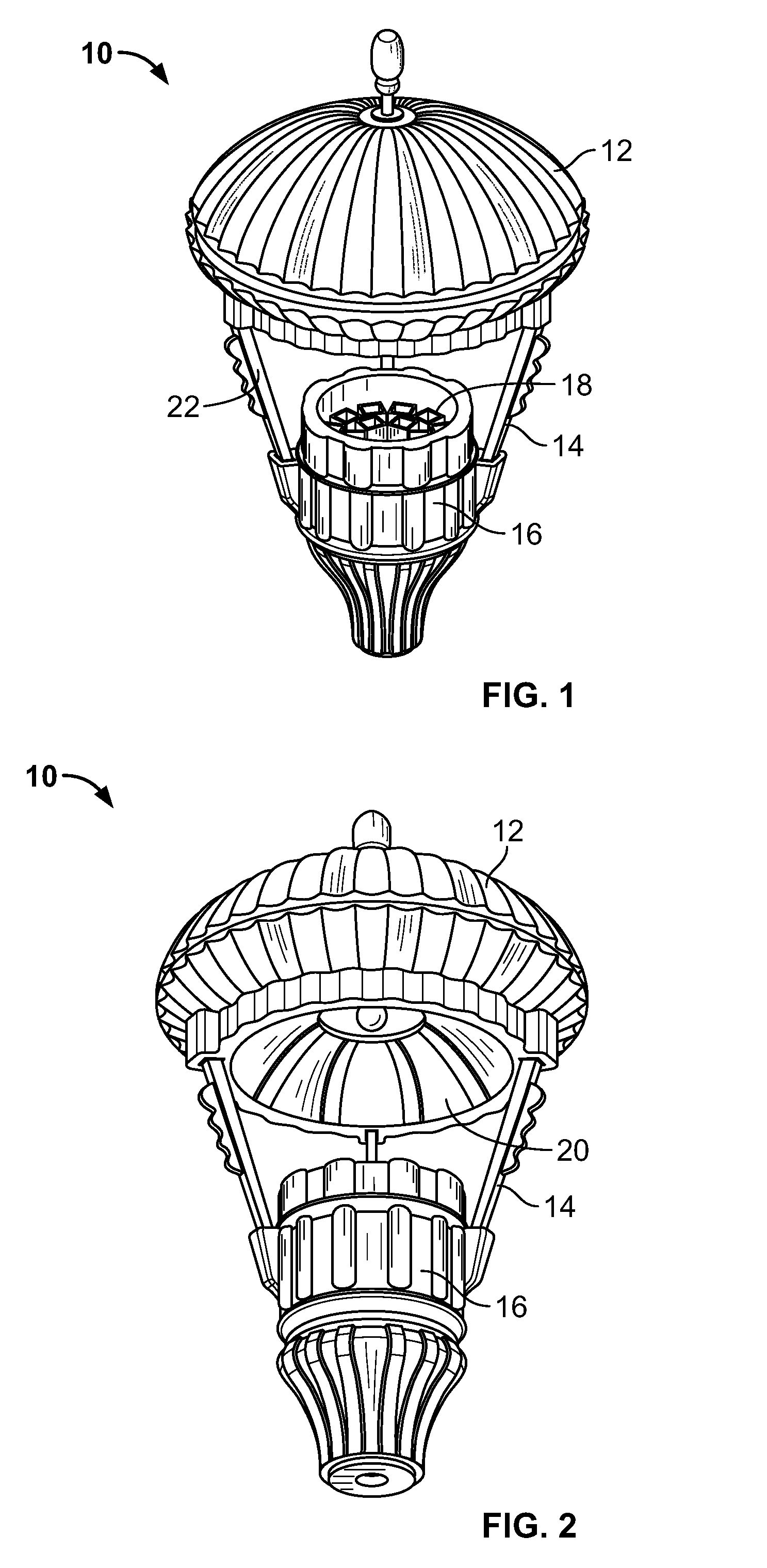
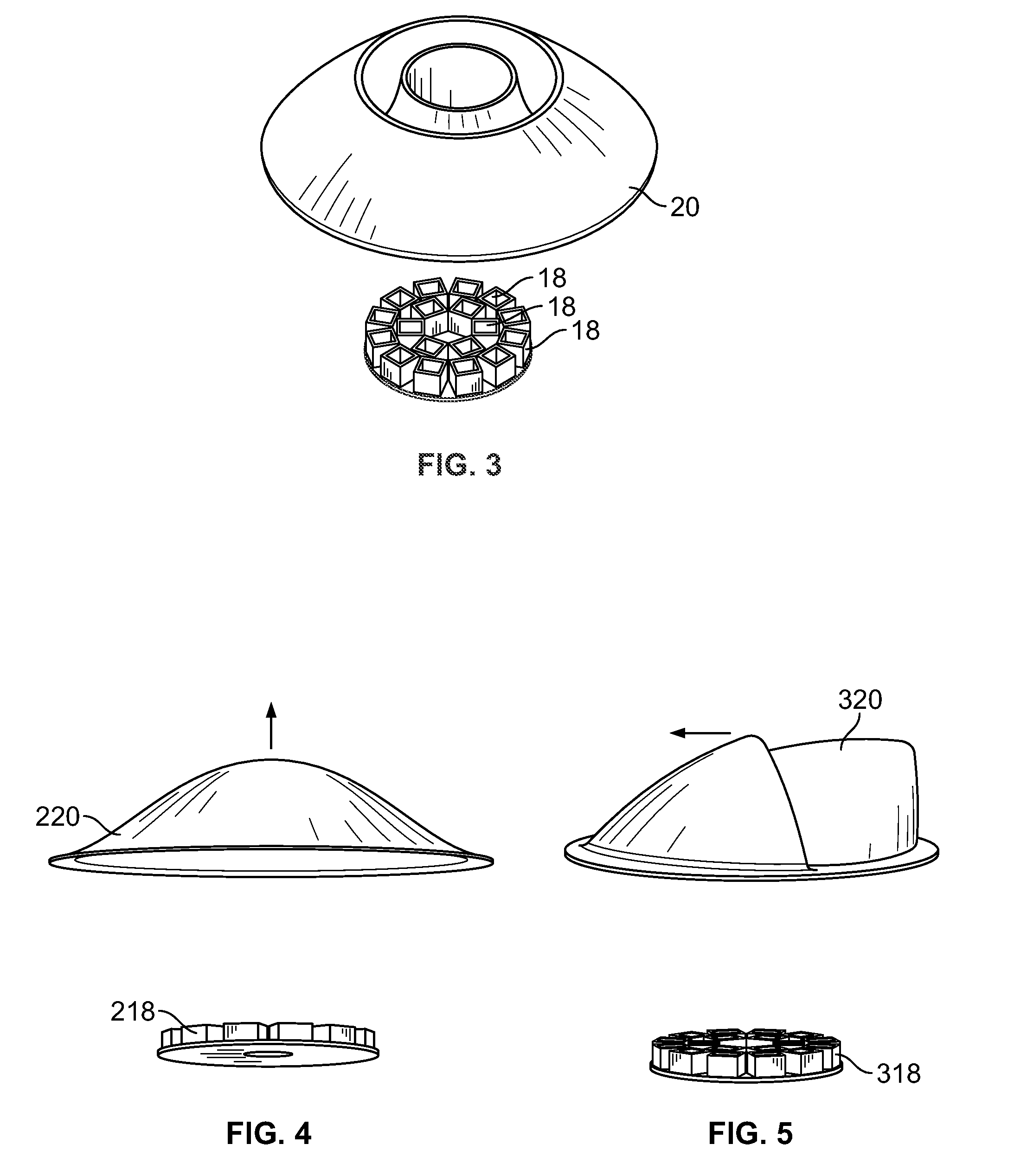
Indirect luminaire utilizing LED light sources

a technology of led light sources and indirect luminaires, applied in the field of led lighting, can solve the problems of high initial cost, lack of lumen output and optical control required for general illumination, and a significant barrier to market entry, understanding and full acceptance of leds

Inactive Publication Date: 2010-01-07
HUBBELL INC
View PDF25 Cites 61 Cited by
  • Summary
  • Abstract
  • Description
  • Claims
  • Application Information

AI Technical Summary

Problems solved by technology

Although the brightness of LEDs have made them a good alternative to incandescent lamps in signaling devices, they have previously lacked the lumen output and optical control required for general illumination.
In addition, their high initial cost was also a significant barrier to market entry.
Early efforts to utilize LEDs for general illumination raised the awareness of LED technology, but the narrow beam distribution and unfounded claims of 100,000+ hour life delayed the understanding and full acceptance of LEDs being used for outdoor area lighting.
Until recently, the light output of LED sources made the technology an inefficient choice for outdoor area lighting.
By rotating the LED arrays, the unshielded brightness results in high levels of glare.
Glare has been known to limit the viewer's ability to see the lighted road or pathway, which can lead to an unsafe condition.

Method used


Image

  • Indirect luminaire utilizing LED light sources
  • Indirect luminaire utilizing LED light sources
  • Indirect luminaire utilizing LED light sources

Examples


Embodiment Construction

[0032]While the present invention is susceptible of embodiment in various forms, there is shown in the drawings and will hereinafter be described a presently preferred embodiment with the understanding that the present disclosure is to be considered an exemplification of the invention and is not intended to limit the invention to the specific embodiment illustrated.

[0033]It should be further understood that the title of this section of this specification, namely, “Detailed Description of the Invention”, relates to a requirement of the United States Patent Office, and does not imply, nor should be inferred to limit the subject matter disclosed herein.

[0034]Rather than using multiple large, angled linear LED arrays to produce the light required for area lighting, the present luminare uses an indirect reflector system to harness the concentrated light from the array of individual LEDs and apply the lumens where needed. The present invention allows for optical control and little to no g...


PUM


Abstract

A luminare uses an indirect reflector system to harness the concentrated light from an array of LED luminaires and direct the lumens where needed. The luminare allows for optical control and little to no glare by re-focusing the concentrated light emitted from each LED luminaire on the reflector at desired angles required for the selected lighting. A satin finish on the reflector diffuses the LED lamp image brightness and increases uniformity of illumination on the ground.

Description

CROSS-REFERENCE TO RELATED APPLICATION[0001]This application claims the benefit of priority of Provisional U.S. Patent Application Ser. No. 61 / 078,537, filed Jul. 7, 2008, entitled “LED LIGHT ENGINE AND HEAT SINK”.BACKGROUND OF THE INVENTION[0002]The present invention is directed to lighting. More particularly, the present invention pertains to LED lighting for architectural and outdoor lighting.[0003]LED (light emitting diode) technology has been widely used in many consumer products for nearly four decades. The most common use for LED has been in indicator lights. The high brightness and point-source characteristics of LEDs have allowed them to be widely accepted in use for traffic signals and in the automotive industry, for example, in tail lights.[0004]Although the brightness of LEDs have made them a good alternative to incandescent lamps in signaling devices, they have previously lacked the lumen output and optical control required for general illumination. In addition, their h...

Claims


Application Information

Patent Timeline
Patent Type & Authority Applications(United States)
IPC IPC(8): F21S8/00F21V29/00F21V7/04
CPCF21S48/328F21V7/0008F21V7/09F21V29/773F21W2131/10F21Y2101/02F21Y2105/001F21V29/004F21Y2105/10F21Y2115/10F21V29/70F21S45/47
Inventor ROMANO, PERRY
Owner HUBBELL INC
Why Eureka
Try Eureka