Receiver Device, System, and Method for Low-Energy Reception of Data

Inactive Publication Date: 2010-01-07
SCHMIDT FRANK
View PDF8 Cites 7 Cited by
  • Summary
  • Abstract
  • Description
  • Claims
  • Application Information

AI Technical Summary

Benefits of technology

[0013]One object of the invention is to provide a receiver device with high sensitivity, wherein the

Problems solved by technology

A problem that has been known for a long time and that it is essential to solve in wireless technology is the construction of receiver devices that feature high sensitivity for the signals to be received, but use little energy themselves for accurate reception of these transmitted signals.
This damping is caused by the free-space transmission and effects due to interference and the surroundings.
Modern wireless systems can definitely reach long ranges, but for this purpose a complicated circuit concept is provided in The receiver devices, wherein these receiver devices themselves require a lot of energy.
If a receiver device is to be built that has available only a little power-supply energy or that is to consume a little energy for the accurate reception of weak-level signals, then long ranges could not be achieved with conventional circuit concepts.
This problem arises especially in energy self-sufficient or battery-operated reception devices that function, for example, according to the energy-harvesting principle.
Higher energy input necessarily leads to higher energy consumption an

Method used


Image

  • Receiver Device, System, and Method for Low-Energy Reception of Data
  • Receiver Device, System, and Method for Low-Energy Reception of Data
  • Receiver Device, System, and Method for Low-Energy Reception of Data

Examples


Example

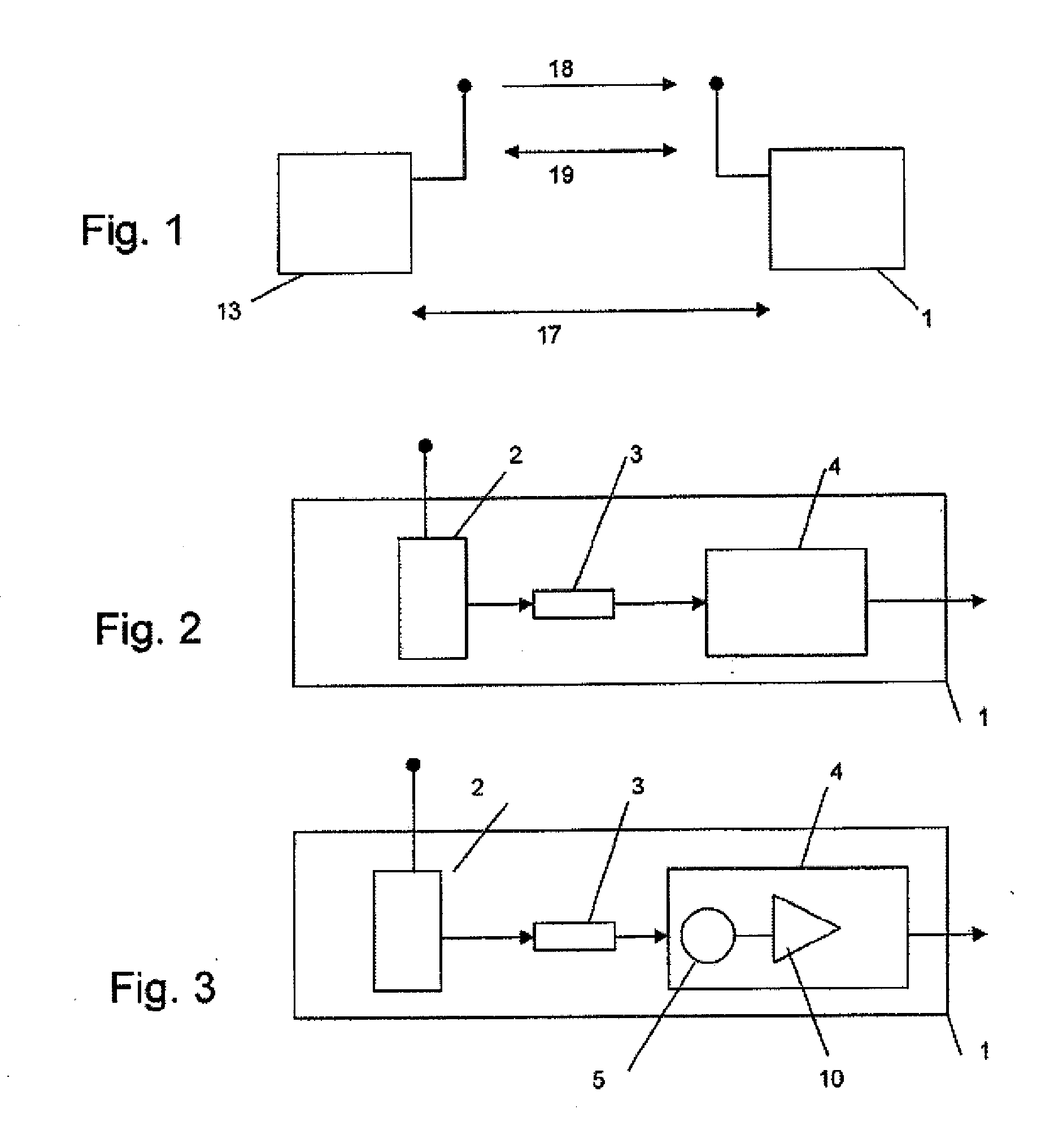
[0055]In FIG. 2, a first embodiment of The receiver device 1 is described. This receiver device 1 includes an antenna 2, a downstream resistive element 3, and an evaluation unit 4 connected after the resistive element 3.

[0056]The antenna 2 converts a variable electromagnetic field quantity into an amplitude-modulated electrical quantity and provides this electrical quantity at the output. The antenna is, for example, a dipole antenna. The downstream resistive element 3 converts this electrical quantity into a physical parameter. As the resistive element, an electrical resistor is preferably used. The downstream evaluation unit 4 evaluates this physical parameter, wherein this parameter varies with the amplitude of the received signal. In FIG. 10, as an example, the varying of the physical parameter temperature 22 is shown as a function of the modulated signal 21. The detected information signal 23 that corresponds to the original signal is provided at the output of the evaluation un...


PUM


Abstract

A receiver device, A system and a method for reception of a signal having an amplitude that has been modulated with information, wherein a resistive element is provided that converts an electrical quantity into a physical parameter.

Description

RELATED APPLICATION[0001]This application claims priority of German Application No. 10 2008 314 06.4 filed Jul. 2, 2008, the content of which is hereby incorporated by reference.FIELD OF THE INVENTION[0002]The invention relates to a receiver device, a system, and a method for the reception of a signal having an amplitude that has been modulated with information.BACKGROUND OF THE INVENTION[0003]Due to existing standards, transmission devices of wirelessly operated systems may not exceed a defined transmission power. A typical maximum transmission power is, for example, 10 mW. This corresponds to a maximum transmission level of 10 dBm. Due to this limitation of the transmission power, the range for successful transmission of information is very greatly dependent on the configuration of The receiver device. A problem that has been known for a long time and that it is essential to solve in wireless technology is the construction of receiver devices that feature high sensitivity for the ...

Claims


Application Information

Patent Timeline
IPC IPC(8): H04B1/16
CPCH03D1/02H04L27/06H03D1/00
Inventor SCHMIDT, FRANK
Owner SCHMIDT FRANK
Why Eureka
Try Eureka