Eureka AIR delivers breakthrough ideas for toughest innovation challenges, trusted by R&D personnel around the world.

Dynamically triggerable NANO RFID device and related method

Inactive Publication Date: 2010-01-14
CARDULLO MARIO W
View PDF11 Cites 18 Cited by
  • Summary
  • Abstract
  • Description
  • Claims
  • Application Information

AI Technical Summary

Benefits of technology

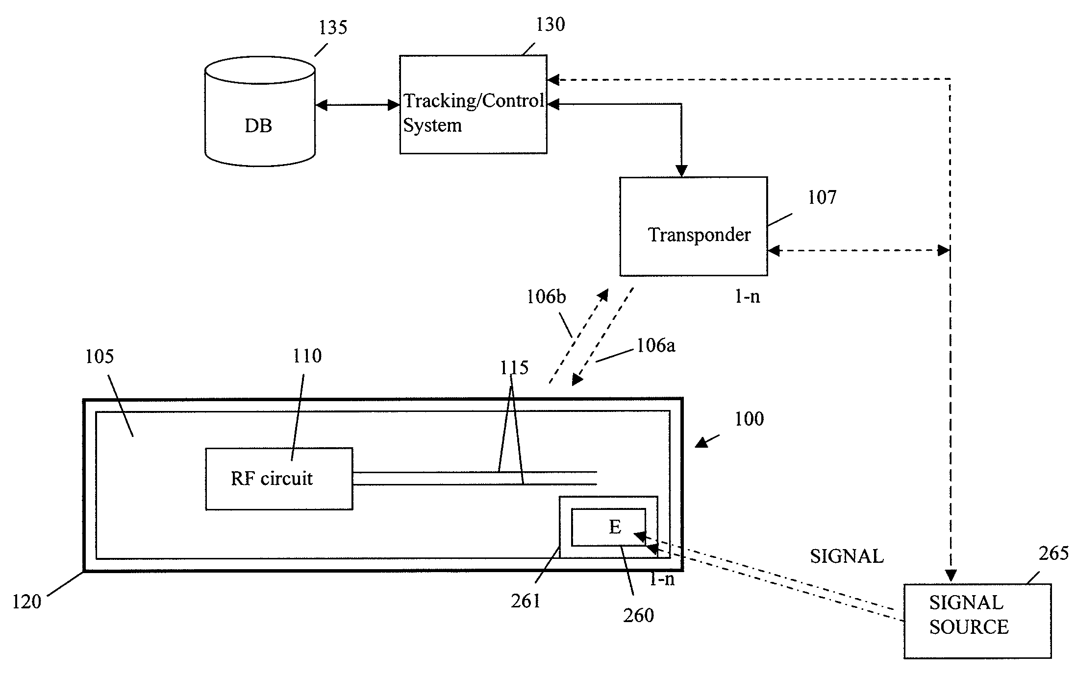
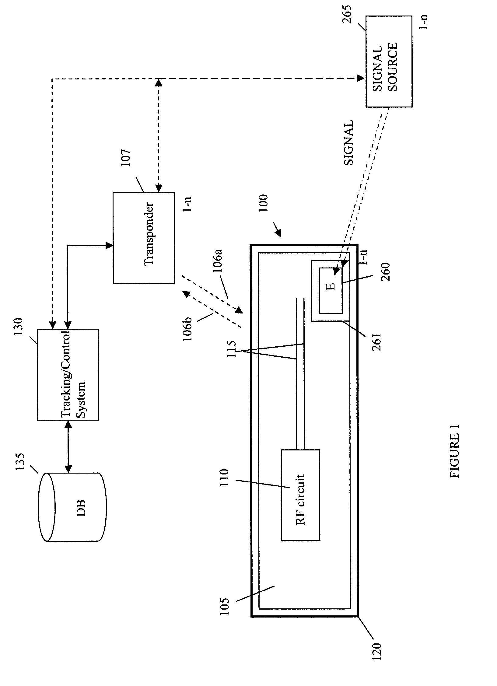
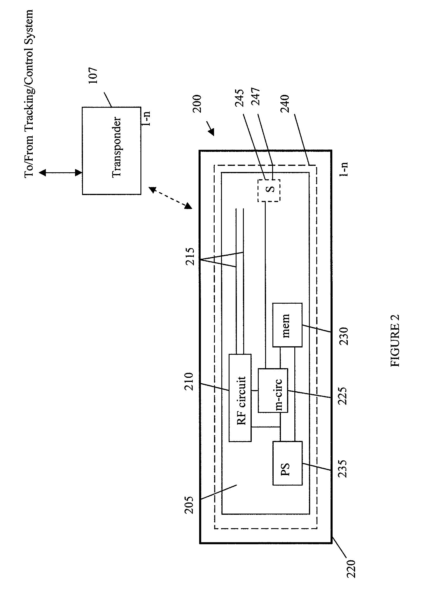
[0011]The invention meets the foregoing need and provides for a nano RFID device and related method suitable for use in applications requiring a tracking device of 200 nanometers or smaller in size. The nano RFID device constructed according to principles of the invention may be embedded in or distributed to a target, including humans, animals, compositions, fabrics, objects, or the like. In some applications, the nano RFID device as constructed according to pri

Problems solved by technology

However, there are few practical techniques for tracking people or animals in a dynamic manner.
In particular, there are few, if any, techniques for covertly tracking a person or an animal with a capability to deliver an effect to the person or animal via an RFID technique, with a capacity to trigger the effect on the person or animal.
Semi-passive tags are similar to active tags in that they have a power source, but it may only power the micro-circuitry and may not power the broadcasting of the signal.
However, the current technology for all these types of tags, passive and active, still requires relatively “large” physical packaging.
Because of the size constraints, applications requiring RFID technology may be unduly restrictive.
Moreover, current tags do not impart any effect on their associated entities.

Method used


Image

  • Dynamically triggerable NANO RFID device and related method
  • Dynamically triggerable NANO RFID device and related method
  • Dynamically triggerable NANO RFID device and related method

Examples


Embodiment Construction

[0025]It is understood that the invention is not limited to the particular methodology, protocols, etc., described herein, as these may vary as the skilled artisan will recognize. It is also to be understood that the terminology used herein is used for the purpose of describing particular embodiments only, and is not intended to limit the scope of the invention. It also to be noted that as used herein and in the appended claims, the singular forms “a,”“an,” and “the” include the plural reference unless the context clearly dictates otherwise. Thus, for example, a reference to “an address” is a reference to one or more addresses and equivalents thereof known to those skilled in the art.

[0026]Unless defined otherwise, all technical and scientific terms used herein have the same meanings as commonly understood by one of ordinary skill in the art to which the invention pertains. The embodiments of the invention and the various features and advantageous details thereof are explained more ...


PUM


Abstract

A nano RFID device or tag and method for using same are disclosed. The nano RFID device may be less than about 150 nanometers in size. The nano RFID device may be a passive, active or semi-passive nano RFID device. The nano RFID device may be distributed to a target such as a human or animal or products, for example. The nano RFID device may include a nano antenna that may comprise one or more carbon tubes. The nano RFID device may include a nano battery. The nano RFID device may include an environmentally reactive layer that reacts to its immediate environment to affix or adhere to a target. The nano RFID device may be constructed for direct or indirect distribution techniques such as by airborne techniques for inhalation, consumption distribution for ingestion, or contact distribution, for example. The nano RFID device may also be constructed to deliver, on command or other certain conditions, an effect such as a virus, compound, toxin or the like, on a target such as a terrorist, for example.

Description

CROSS-REFERENCE TO RELATED APPLICATIONS[0001]This application claims benefit and priority to U.S. Provisional No. 61 / 079,936, filed Jul. 11, 2008, entitled DYNAMICALLY TIGGERABLE NANO RFID DEVICE AND RELATED METHOD, the disclosure of which is incorporated by reference herein, in its entirety.BACKGROUND OF THE INVENTION[0002]1. Field of the Invention[0003]The invention is directed generally to a device and method related to nano radio frequency identification (RFID) technology and, more specifically, to a nano RFID device and method for dynamically distributing and triggering the nano RFID device to facilitate covert tracking and / or identification of a target subject, such as a person or an animal, including dynamically triggering the nano RFID device to impart an effect on a target subject, such as a terrorist, for example.[0004]2. Related Art[0005]Many systems and methods exist for tracking inanimate items such as packages or shipping containers using radio frequency identification...

Claims


Application Information

Patent Timeline
IPC IPC(8): H04Q5/22
CPCH04Q9/00H04Q2209/47H04Q2209/20
Inventor CARDULLO, MARIO W.
Owner CARDULLO MARIO W
Why Eureka
Eureka Blog
Learn More