Temperature probe for an oven, oven and method for operating an oven

a technology for ovens and probes, applied in the field of oven temperature probes, can solve the problems of difficult operation of ovens, difficulty in adjusting the temperature of ovens, and inability to explain the operation of an energy supply, etc., and achieve the effect of convenient and better handling

Inactive Publication Date: 2010-01-21
E G O ELEKTRO GERAETEBAU GMBH
View PDF6 Cites 42 Cited by
  • Summary
  • Abstract
  • Description
  • Claims
  • Application Information

AI Technical Summary

Benefits of technology

[0005]The object of the invention is to provide a previously mentioned temperature probe, a previously mentioned oven, as well as a previously mentioned method with which the disadvantages of prior art can be avoided and with which, in particular, a temperature probe that allows easier and better handling can be provided.
[0007]In accordance with one embodiment of the invention, the temperature probe comprises an energy generation device for the emitting means, said energy generation being configured in such a manner that it draws or generates energy from its environment in the oven during operation of the oven. This means that sensitive power storages such as batteries or chargeable batteries can be omitted and, still, electrical power can be generated for operation of the emitting means. The energy can be generated using other energy sources that are already present in the oven, as will be explained in greater detail hereinafter. The main issue here is the new type of energy generation. Thus, it is possible with the invention to provide a wireless temperature probe that can be used in many ways and whose temperature information is wirelessly transmitted to an oven control device. Complex or expensive and potentially technically sensitive solutions such as transponders, emitting devices featuring surface-wave technology, or the like can be avoided.
[0015]It is considered advantageous when the first disk or thermogenerator is at a specific distance from the free end of the temperature probe, for example, a few centimeters. As a result of this, an emitting device or an antenna of the emitting means may transmit temperature information unhindered and also with the lowest required emitting power. Alternatively, a disk or a housing part may be used as the antenna.
[0016]In accordance with a different approach of generating energy, it is possible to utilize a photovoltaic effect in order to generate electrical power from the light in the oven. To this end, the light in the oven or an ambient light coming through a light-transmitting oven door may be added. For the photovoltaic effect, it may be advantageous to use a solar cell. Such a solar cell—in a manner similar as previously described for the thermogenerator—can be advantageously placed at a distance from the end that has been inserted into the food product. It is considered advantageous when the electrical properties of the solar cell are adapted to the light or the wavelength of the light that prevails in the oven. Furthermore, the orientation of the solar cell may be variable or may be aligned in such a manner that it is positioned so as to be as perpendicular as possible to a light source in the oven to attain the best-possible incident light or the highest-possible energy yield. To accomplish this, it is alternatively possible for the surface of the solar cell to be positioned in an inclined manner relative to the longitudinal axis of the temperature probe that advantageously has a straight configuration. This means that it is possible, by rotating the temperature probe about its longitudinal axis—as is easily possible when said probe is inserted in the food product—to carry out an alignment without requiring mechanically movable joints or the like.
[0024]In another embodiment of the invention, the oven may comprise a detecting device at the storage area. As a result of this, it is possible to detect when the oven is being operated, regardless of whether the temperature probe—at least a front region of the temperature probe comprising the electronic device or the temperature sensor—is located in or plugged into said storage area. This detecting device may be connected to an oven control device and, during operation of the oven, prevent the oven from being heated to high temperatures when the temperature probe is not in the storage area.
[0027]In order to save energy, the emission of the temperature information by means of the emitting means may either occur continuously or also at certain time intervals, in particular, periodically. Furthermore, it is possible for short-term energy storage in the temperature probe to occur, for example, via a thermally stable capacitor. This means that, for a periodic operation of the emitting means, it is possible to collect energy for an extended time to be used later for a short time for emission, for example, for emission every one to 30 seconds.

Problems solved by technology

However, it is disadvantageous in this case that such a temperature probe is tied to a cable.
However, the use of power storage devices, such as batteries or the like, for a transmitting device, is difficult in the oven because they would be destroyed with the occurring temperatures of over 200° C.
However, the entire disclosure does not explain how an energy supply could be implemented with a thermogenerator.
The main issue here is the new type of energy generation.
Due to the lacking temperature difference, said probe cannot emit any temperature information because it cannot generate any electrical power.
Furthermore, the problem exists here that the temperature probe is fully exposed to the temperature of the interior of the oven and may thus overheat, this leading to the potential damage or destruction.

Method used


Image

  • Temperature probe for an oven, oven and method for operating an oven
  • Temperature probe for an oven, oven and method for operating an oven
  • Temperature probe for an oven, oven and method for operating an oven

Examples


Embodiment Construction

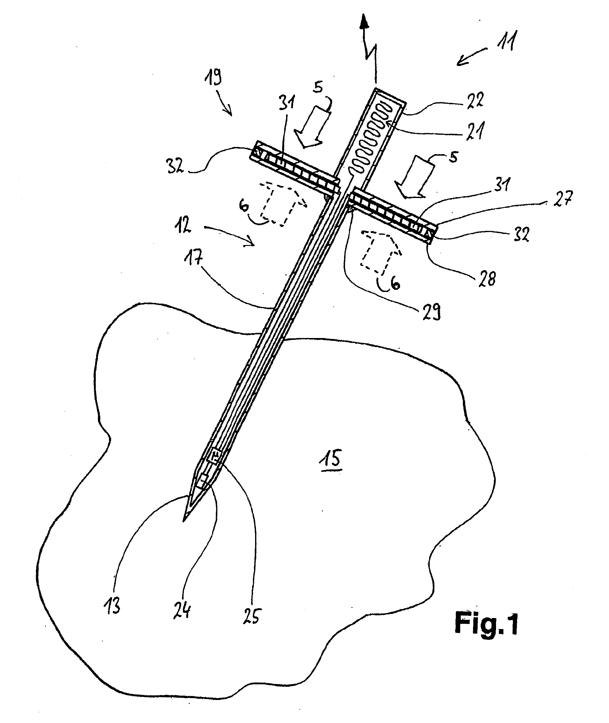
[0037]FIG. 1 shows a temperature probe 11 in accordance with one embodiment of the invention, said temperature probe being constructed in the manner of a so-called roast spit. The temperature probe 11 comprises a longitudinal, pipe-like housing 12 that terminates in a tip 13 toward the front. Said tip is inserted into a roast 15 that is the food product to be cooked. The housing comprises a housing jacket 17 of a metal that is suitable for the operating conditions of a roasting spit, for example, copper, for improved heat conductivity, possibly also coated, or provided with a thin stainless steel sleeve for foodstuff hygiene. A disk-shaped energy generator 19 adjoins the housing. This energy generator, in turn, has a terminal cap 22 in which the emitting means 21 are arranged—as would be an antenna or the like—in order to protect said emitting means.

[0038]A temperature sensor 24 is provided in the tip 13 of the temperature probe 11, said sensor being connected to an electronic devic...


PUM

PropertyMeasurementUnit
temperatureaaaaaaaaaa
temperaturesaaaaaaaaaa
sizeaaaaaaaaaa

Abstract

The invention relates to a temperature probe for an oven, comprising in one embodiment a longitudinal housing in the form of a spit. A temperature sensor and an electronic unit are arranged in a tip and are connected at the other end to emitting means. The temperature probe comprises a thermogenerator for producing energy. The thermogenerator uses a temperature difference between a higher temperature inside the oven and a lower core temperature in a food product, such as roast, in which the temperature probe is inserted, for producing energy for operating the emitting means.

Description

CROSS REFERENCE TO RELATED APPLICATIONS[0001]This application is a continuation of PCT / EP2008 / 001886, filed Mar. 10, 2008, which in turn claims priority to DE 10 2007 016 452.3, filed on Mar. 30, 2007 and DE 10 2007 018 245.9, filed Apr. 12, 2007, the contents of which are incorporated by reference.FIELD OF THE INVENTION[0002]The invention relates to a temperature probe for an oven, where said temperature probe can be inserted in the food product to be cooked, as well as to an oven comprising such a temperature probe and to a method for controlling such an oven.BACKGROUND OF THE INVENTION[0003]U.S. Pat. No. 5,495,038 discloses an oven with a temperature probe as the so-called roast spit. During the cooking process or during operation of the oven with a food product such as, for example, a roast, a longitudinal, spit-like temperature probe is inserted into the food product, said probe having a temperature sensor in its tip allowing it to detect the temperature of said food product. T...

Claims


Application Information

Patent Timeline
Patent Type & Authority Applications(United States)
IPC IPC(8): A21B1/00G01K13/00
CPCG01K1/024G01K1/14G01K2215/00G01K2207/06G01K13/00
Inventor BAIER, MARTIN
Owner E G O ELEKTRO GERAETEBAU GMBH
Why Eureka
Try Eureka