Load control device having audible feedback

a technology of audible feedback and control device, which is applied in the direction of process and machine control, instruments, pulse techniques, etc., can solve the problems of inability to provide an acceptable amount of sensory feedback to the user in the early stages of touch dimmers

Inactive Publication Date: 2010-01-21
LUTRON TECH CO LLC
View PDF31 Cites 35 Cited by
  • Summary
  • Abstract
  • Description
  • Claims
  • Application Information

AI Technical Summary

Problems solved by technology

However, prior art touch dimmers have suffered from not being able to provide an acceptable amount of sensory feedback to the user.

Method used


Image

  • Load control device having audible feedback
  • Load control device having audible feedback
  • Load control device having audible feedback

Examples


first embodiment

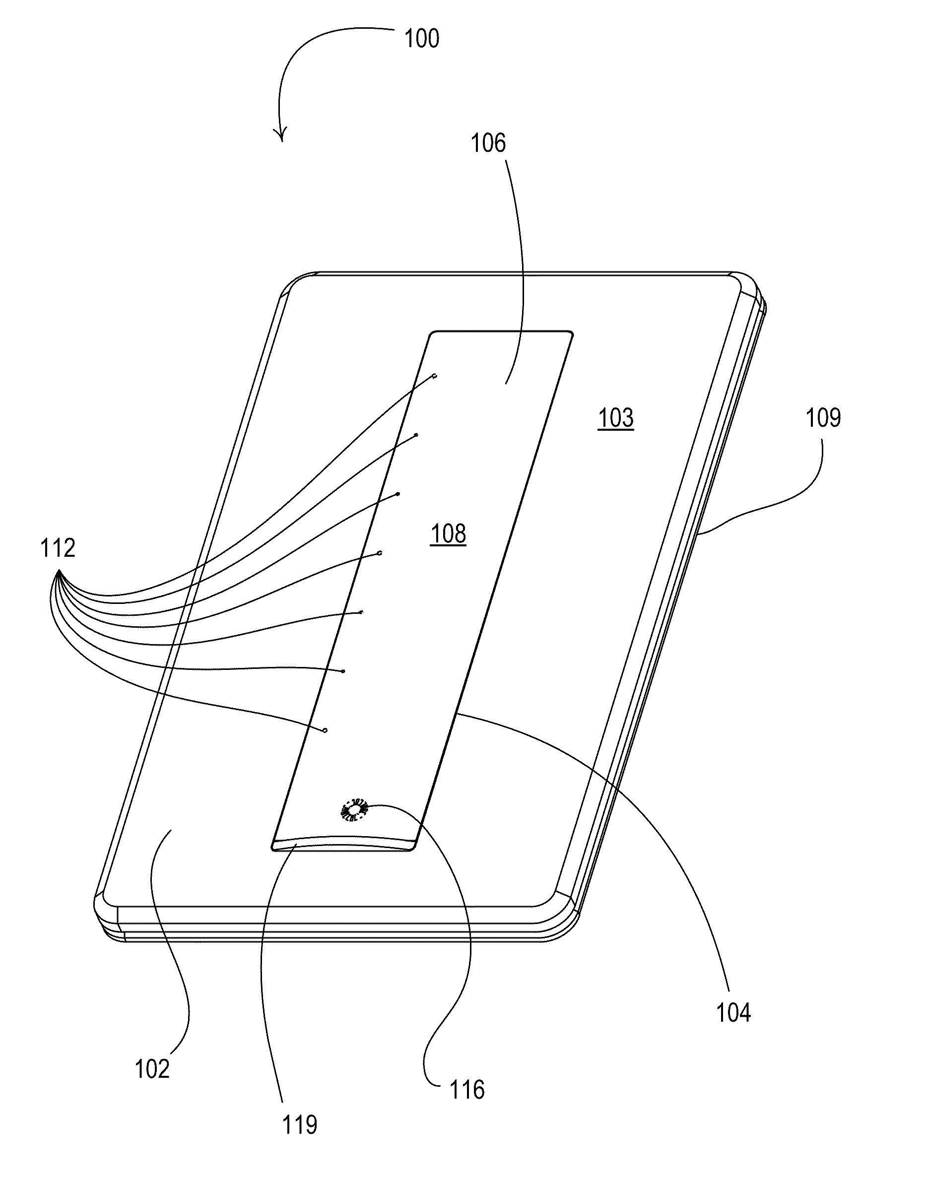
[0075]FIGS. 4A and 4B are a perspective view and a front view, respectively, of a touch dimmer 100 according to the present invention. The dimmer 100 is operable to be connected between an AC voltage source 204 (FIG. 7) and a lighting load 208 (FIG. 7) for turning the lighting load on and off The dimmer 100 is also operable to control the amount of power delivered to the lighting load any desired value between and including maximum and minimum values. As a result, the dimmer 100 is able to control an intensity L of the lighting load between a minimum (i.e., low-end) intensity LMIN (e.g., 1%) and a maximum (i.e., high-end) intensity LMAX (e.g., 100%). The dimmer 100 includes a faceplate 102, i.e., a cover plate, having a planar front surface 103 and an opening 104. The opening 104 may define a standard industry-defined opening, such as a traditional opening or a decorator opening, or another uniquely-sized opening as shown in FIG. 4A.

[0076]The dimmer 100 comprises a control structure...

second embodiment

[0133]FIG. 19 is a perspective view and FIG. 20 is a front view of a touch dimmer 700 according to the present invention. FIG. 21 is a bottom cross-sectional view and FIG. 22 is an enlarged partial bottom cross-sectional view of the dimmer 700. FIG. 23 is a left side cross-sectional view and FIG. 24 is an enlarged partial left side cross-sectional view of the dimmer 700.

[0134]The touch dimmer 700 includes a thin touch sensitive actuator 710 comprising an actuation member 712 extending through a bezel 714. The dimmer 700 further comprises a faceplate 716, which has a non-standard opening 718 and mounts to an adapter 720. The bezel 714 is housed behind the faceplate 716 and extends through the opening 718. The adapter 720 connects to a yoke 722, which is adapted to mount the dimmer 700 to a standard electrical wallbox. A main printed circuit board (PCB) 724 is mounted inside an enclosure 726 and includes the some of the electrical circuitry of the dimmer 200, e.g., the semiconductor s...

third embodiment

[0138]FIG. 26A is a perspective view and FIG. 26B is a front view of a lamp control module 800 according to the present invention. The lamp control module 800 has a body 814 which contains screw-in base 810, such that the lamp control module is adapted to be screwed into a standard Edison socket. The lamp control module 800 also includes a socket portion 820 (e.g., a standard Edison socket), such that a lighting load 904 (FIG. 27), for example, a standard incandescent lamp, may be coupled to and controlled by the lamp control module. The lamp control module 800 comprises a controllably conductive device 910 (FIG. 27), which is contained within a housing 814 and provides for control of the amount of power delivered to the lighting load 904. When the lamp control module 800 is screwed into a standard Edison socket that is powered by an AC power source 902 (FIG. 27), such as an AC mains voltage (e.g., 120 VAC at 60 Hz), and the lighting load 904 is screwed into the socket portion, the ...


PUM


Abstract

A load control device for controlling the amount of power delivered from an AC power source to an electrical load comprises a non-visual, haptic sensory output structure for producing a variable human detectable output related to the amount of power being delivered to the load. Specifically, the load control device may comprise an audible sound generator for generating audible sounds having operational characteristics that are representative of the amount of power being delivered to the load. For example, the amplitude (or frequency) of the audible sounds may increase as the amount of power delivered to the load increases and may decrease as the amount of power delivered to the load decreases. The audible sound generator may generate a turn-on audible sound that increases in amplitude (or frequency) with respect to time when the load is turned on, and a turn-off audible sound that decreases in amplitude (or frequency) with respect to time when the load is turned off.

Description

CROSS-REFERENCE TO RELATED APPLICATIONS[0001]This is a continuation-in-part of commonly-assigned, co-pending U.S. patent application Ser. No. 11 / 472,245, filed Jun. 20, 2006, entitled TOUCH SCREEN WITH SENSORY FEEDBACK. The present application is also a continuation-in-part of commonly-assigned, co-pending U.S. patent application Ser. No. 12 / 033,329, filed Feb. 19, 2006, entitled SMART LOAD CONTROL DEVICE HAVING A ROTARY ACTUATOR. The entire disclosures of both applications are hereby incorporated by reference.BACKGROUND OF THE INVENTION[0002]1. Field of the Invention[0003]The present invention relates to load control devices for controlling the amount of power delivered to an electrical load from a power source. More specifically, the present invention relates to a dimmer switch operable to provide audible feedback regarding the amount of power being delivered to a connected lighting load.[0004]2. Description of the Related Art[0005]A conventional two-wire dimmer has two terminals:...

Claims


Application Information

Patent Timeline
Patent Type & Authority Applications(United States)
IPC IPC(8): G08B21/00
CPCG06F3/041H01H2215/03H01H2215/044H01H2231/052Y02B20/44H05B37/0209H05B39/04H05B39/085H03K17/96G06F3/045H05B47/165H05B47/17Y02B20/40
Inventor SPIRA, JOEL S.
Owner LUTRON TECH CO LLC
Why Eureka
Try Eureka