Dual frequency antenna system

a dual-frequency antenna and antenna technology, applied in the direction of antenna details, non-resonant long antennas, antennas, etc., can solve the problems of high drag, physical interference with other devices on flying equipment, physical interference with other features of equipment,

Inactive Publication Date: 2010-01-21
GENERAL DYNAMICS C4 SYSTEMS
View PDF8 Cites 3 Cited by
  • Summary
  • Abstract
  • Description
  • Claims
  • Application Information

AI Technical Summary

Problems solved by technology

This sort of design gives rise to high drag when the equipment is in use, as the protrusion affects the aerodynamic nature of the equipment.
Also, this sort of design can cause physical interference with other devices on the flying equipment, as the antenna is an external device placed on the equipment's outer hull.
In situations where these antennas are initially housed within the body of the flying equipment, to be later deployed for communication purposes, deployment can cause physical interference with other features of the equipment, as pre-deployment space for the antennas cannot be used for other payloads.
As a result, these antennas are often unable to provide their greatest gain in both the aft and forward directions, but rather only in a single direction.
However, often the configurations available in conventional dual-band helical antennas are less than desirable.
This addresses the need for dual band; however it significantly increases the length of the antenna.
However, due to the coupling between the transmitter and receiver, if the antenna were to transmit and receive signals simultaneously significant interference could occur between the signals, degrading the integrity of the communication.
While separate filters can be used to increase this isolation, they are undesirable because of their size, weight, cost and attenuation of the signal.
These are problematic solutions because a permanent fixture upon the surface of a flying object increases the drag of the object, and a deployment mechanism may interfere with other functions of the device.
Flying equipment is generally restricted to small weight and size limitations, as the larger and heavier an object is, the more costly the equipment is.
This increases the weight and complexity of the flying equipment, as proper shielding and housing must be created to ensure that the components are held safely.
The process of tuning an antenna becomes more difficult when multiple antennas operating at different frequencies are brought together into a system.
The complexity of the tuning process increases when the antennas are closely positioned together in the system.

Method used


Image

  • Dual frequency antenna system
  • Dual frequency antenna system
  • Dual frequency antenna system

Examples


Embodiment Construction

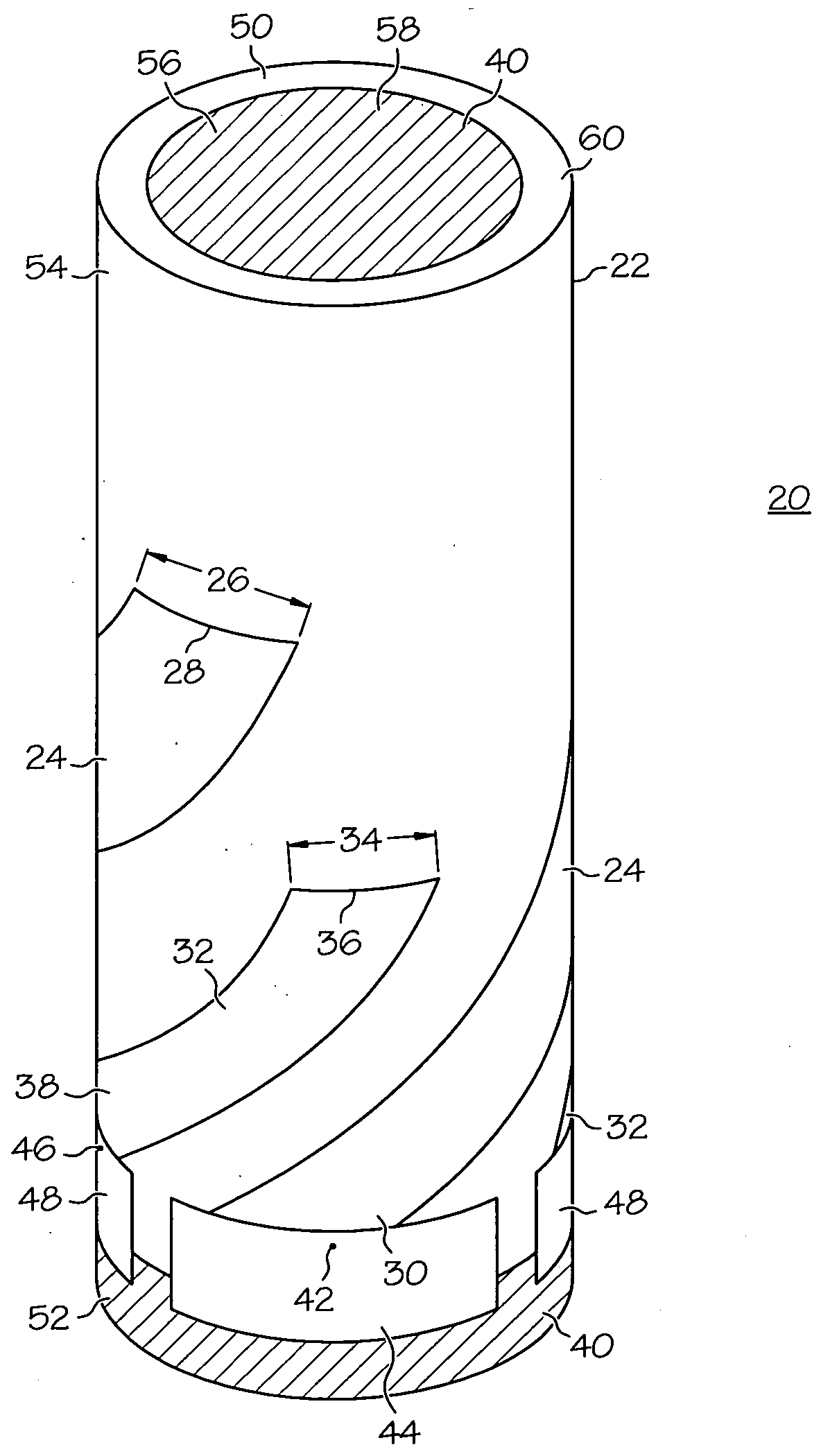
[0020]FIG. 1 is a planar representation of one antenna 62 in antenna system 20 (shown in FIG. 3). First antenna 62 includes a set of radiating conductors 24, and a signal distribution circuit 64. Signal distribution circuit 64 can include a power amp, filter network, and / or any other circuitry (not shown) necessary to ensure that first antenna 62 can communicate to any station. In one embodiment, first antenna 62 is a bifilar antenna, and signal distribution circuit 64 includes passive RF devices to split a signal with equal power division and 180° phase relationship between the set of radiating conductors 24. Radiating conductors 24 are made of a conductive material and each conductor 24 has a length 74, a width 26 (shown in FIG. 4), an open end 28, a shorted end 29 and a feed end 30. In one embodiment, radiating conductors 24 are made from conductive material printed on a dielectric microstrip substrate 60. In another embodiment, the conductive material is simply attached to the d...


PUM


Abstract

A dual-frequency conformal multi-filiar helical antenna system (20) provides a low-profile, low drag antenna useable in flying equipment. This antenna system (20) securely holds within its shell (22) signal distribution circuitry (64), signal combining circuitry (68), and any other circuit components necessary for antenna system (20) to communicate with other stations or devices. Antenna system (20) has radiating conductors (24, 32) tuned to two different frequencies such that simultaneous transmission and reception of signals is possible in the same and opposite directions.

Description

GOVERNMENT RIGHTS[0001]This invention was made with Government support under F08630-03-C-0120 awarded by the Air Force. The Government has certain rights in this invention.TECHNICAL FIELD OF THE INVENTION[0002]The present invention relates to the field of antenna systems. More specifically, the present invention relates to antenna systems having at least two antennas wrapped around a shell, each antenna operating at a different frequency.BACKGROUND OF THE INVENTION[0003]Many contemporary devices have been developed to rely not only on earth-orbiting satellites for navigation purposes, but also ground-based stations for inter-device communication. Specialized products have been created to address communication between a flying object and both earth-based stations and earth-orbiting satellites.[0004]Contemporary antennas used on flying equipment typically have a blade design, such that the antenna protrudes off the surface of the equipment with the edge of the blade design facing the ...

Claims


Application Information

Patent Timeline
Patent Type & Authority Applications(United States)
IPC IPC(8): H01Q1/36
CPCH01Q5/00H01Q5/40H01Q11/08
Inventor MUNGER, ARCHER DAVIDHOUSE, KEVIN DUANETHOMPSON, RUSSELL THOMAS
Owner GENERAL DYNAMICS C4 SYSTEMS
Why Eureka
Try Eureka