Patch antenna

a patch antenna and antenna technology, applied can solve the problems of difficulty in achieving certain desirable effects of patch antennas existing in the field of patch antennas

Active Publication Date: 2008-08-28
MARK IV IVHS
View PDF8 Cites 89 Cited by
  • Summary
  • Abstract
  • Description
  • Claims
  • Application Information

AI Technical Summary

Benefits of technology

[0009]In yet another aspect, the present invention provides a dual-band antenna with a top conductive patch having defined therein a circular slot and four parasitic slots, the four parasitic slots being disposed outside the perimeter of the circular slot and spaced apart therefrom, the four parasitic slots being arc slots having a common radial center with the circular slot and having a length less than their radius times π/2. The antenna also includes a rectangular ground plane, parallel to and spaced apart from the top con

Problems solved by technology

Existing patch antennas have difficulty in achieving certain desirable characteristics, such as vertical polarization relative to a horizontal patch posi

Method used


Image

  • Patch antenna
  • Patch antenna
  • Patch antenna

Examples


Embodiment Construction

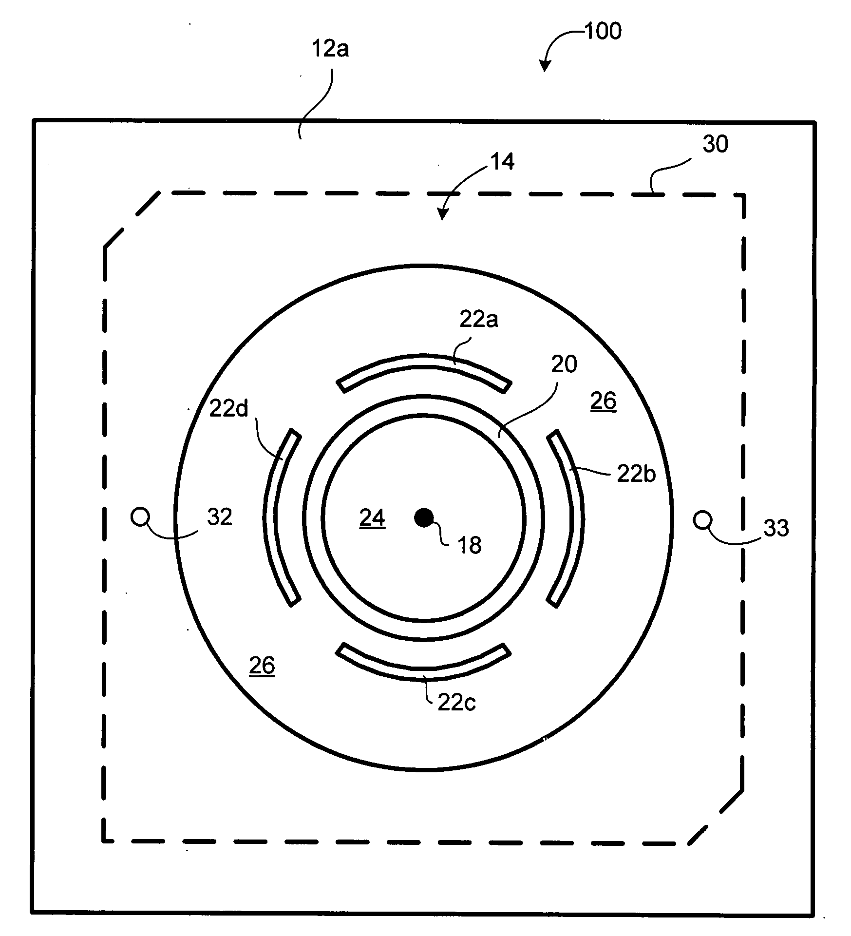
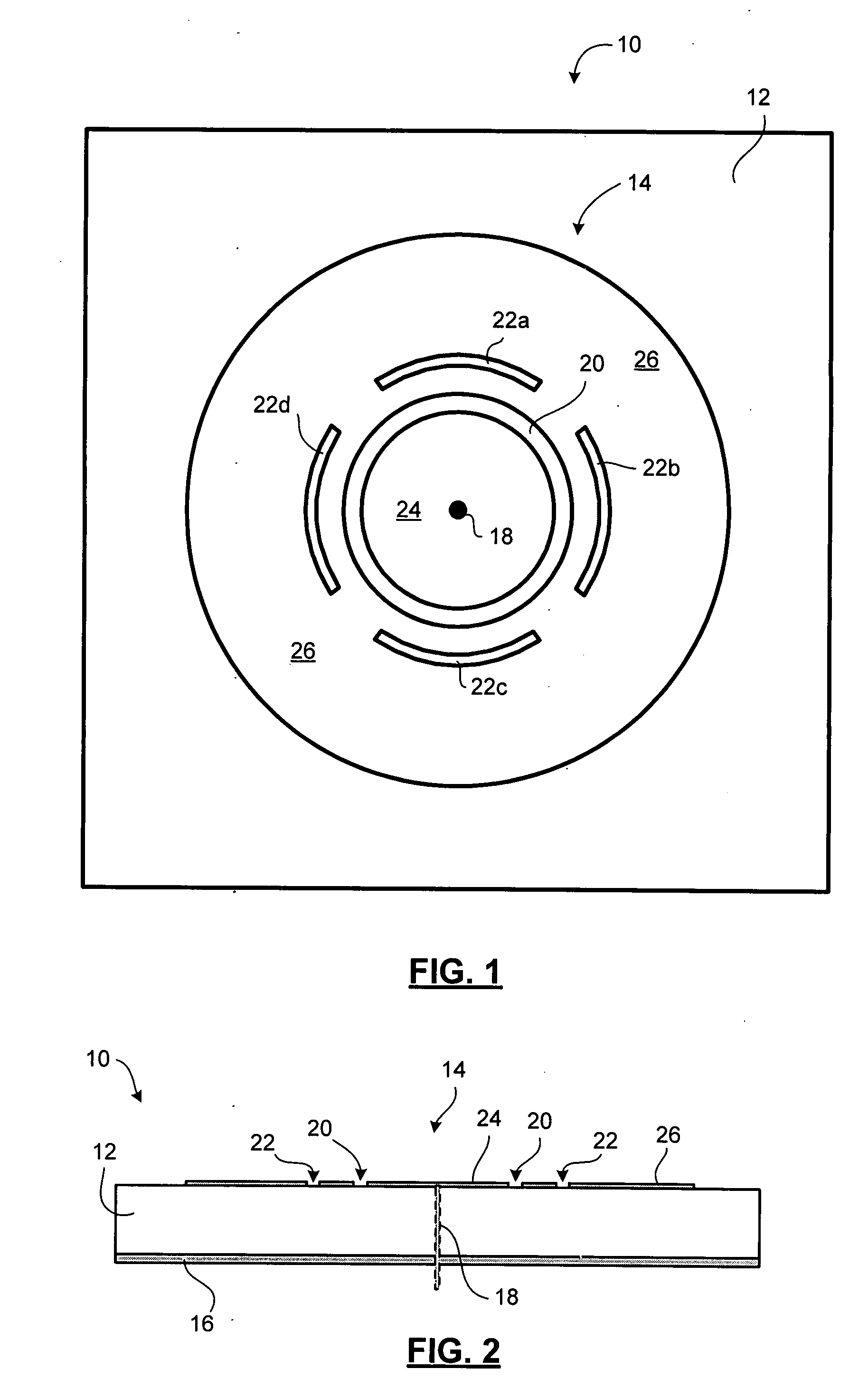
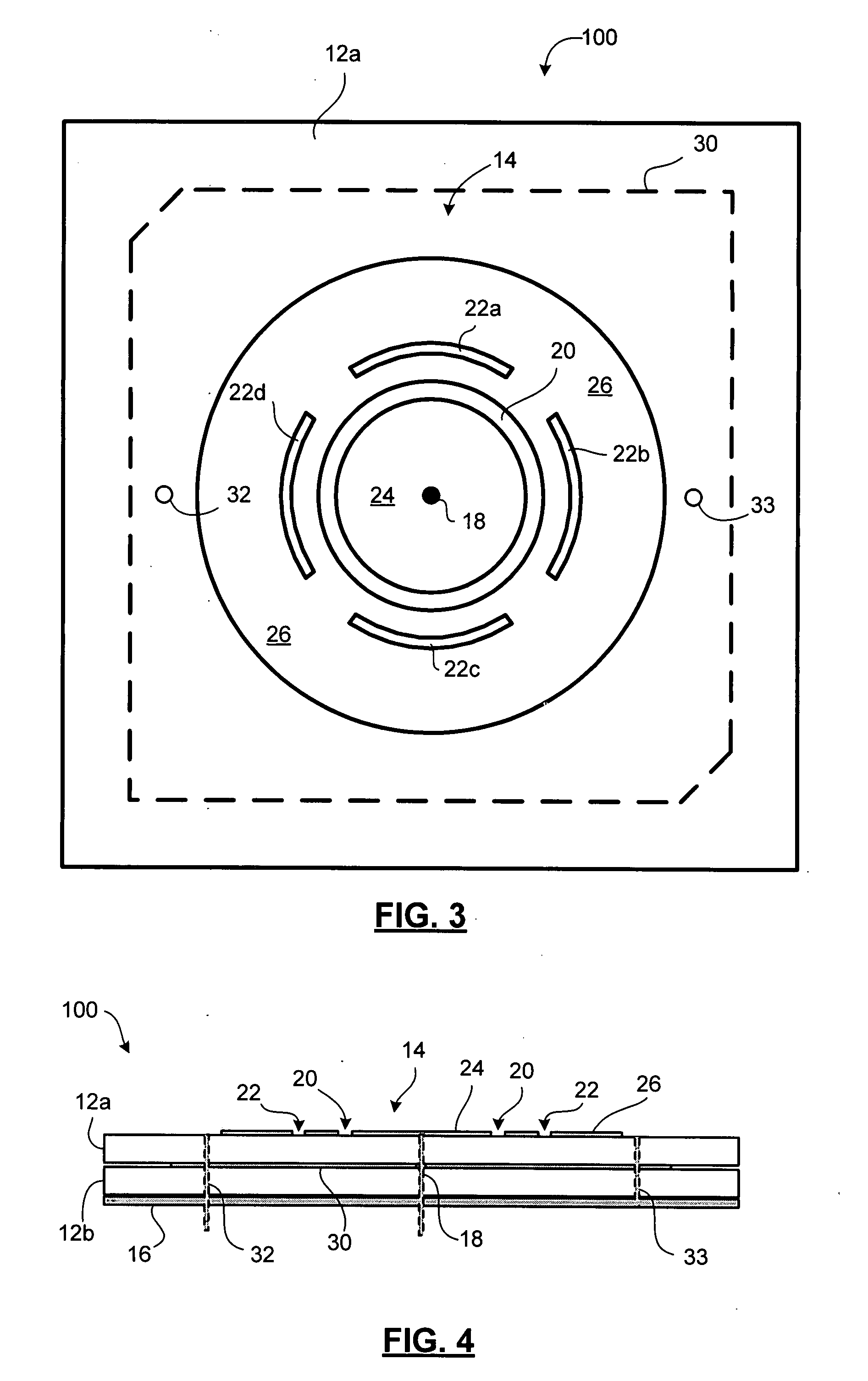
[0019]The following description makes reference to the radiating element of the antenna being a “conductive” patch. In many embodiments, the patch may be formed from a metal or metal alloy; however, in some embodiments, the patch may be formed from non-metallic electrical conductors such as superconductors. There are also other types of non-metallic electrical conductors that may be used in some specific embodiments. Accordingly, references herein to a “conductive patch” may be understood as including metallic and non-metallic electrical conductors.

[0020]The following description also makes reference to feed points and, in particular, coaxial feed probes connected to a patch. It will be appreciated that other feed mechanisms may be used in other embodiments. For example, particular embodiments may use microstrip feeds, coplanar waveguide feeds, electromagnetic coupling feeds, and / or aperture coupling feeds. The selection of a suitable feed mechanism for a particular application will...


PUM


Abstract

A patch antenna for achieving a vertically-polarized radiation pattern is described. The patch antenna includes a closed-curve slot within which a signal feed point is located. Parasitic slots are disposed outside or inside the closed-curve slot. In one embodiment, the closed-curve slot is a ring slot and the parasitic slots are arc slots having a common center point with the ring slot. The antenna may further include a lower patch capable of producing a different radiation pattern with different polarization and at a different frequency band, to result in a dual-band antenna. The dual-band antenna may operate in the 5.9 GHz DSRC and 1.575 GHz GPS bands.

Description

FIELD OF THE INVENTION[0001]The present invention relates to patch antennas and, in particular, to a vertically-polarized patch antenna.BACKGROUND OF THE INVENTION[0002]The proliferation of radio-frequency based technology, such as cellular telephones, RFID devices, and other wireless devices, has led to a number of developments in antenna design. One popular antenna type is the patch antenna, whereby a radiating patch is positioned parallel to and spaced apart from a ground plane. A dielectric substance is placed between the patch and the ground plane. Signals may be provided to the patch, and incoming signals may be obtained, through a feed mechanism. Typical feed mechanisms for patch antennas include one or more coaxial feeds extending through the dielectric material, or an embedded planar feed line connected or electromagnetically coupled to the patch, or an aperture coupled feed.[0003]At present, standards have been developed that apply to communication in a number of different...

Claims


Application Information

Patent Timeline
IPC IPC(8): H01Q13/10
CPCH01Q9/0414H01Q19/005H01Q13/103H01Q9/0428
Inventor ZEINOLABEDIN RAFI, GHOLAMREZASAFAVI-NAENI, SAFIEDDINMALARKY, ALASTAIR
Owner MARK IV IVHS
Why Eureka
Try Eureka