
Systems and methods that employ a dualband IFA-loop CDMA antenna and a GPS antenna with a device for mobile communication

a dual-band ifa-loop, cdma antenna technology, applied in the direction of resonant antennas, independent non-interacting antenna combinations, instruments, etc., can solve the problem of user hand interference and other problems, and achieve the effect of reducing antenna and device size, cost, components, and improving reception and reliability

Inactive Publication Date: 2005-02-24
NOKIA CORP
View PDF30 Cites 85 Cited by
  • Summary
  • Abstract
  • Description
  • Claims
  • Application Information

AI Technical Summary

Benefits of technology

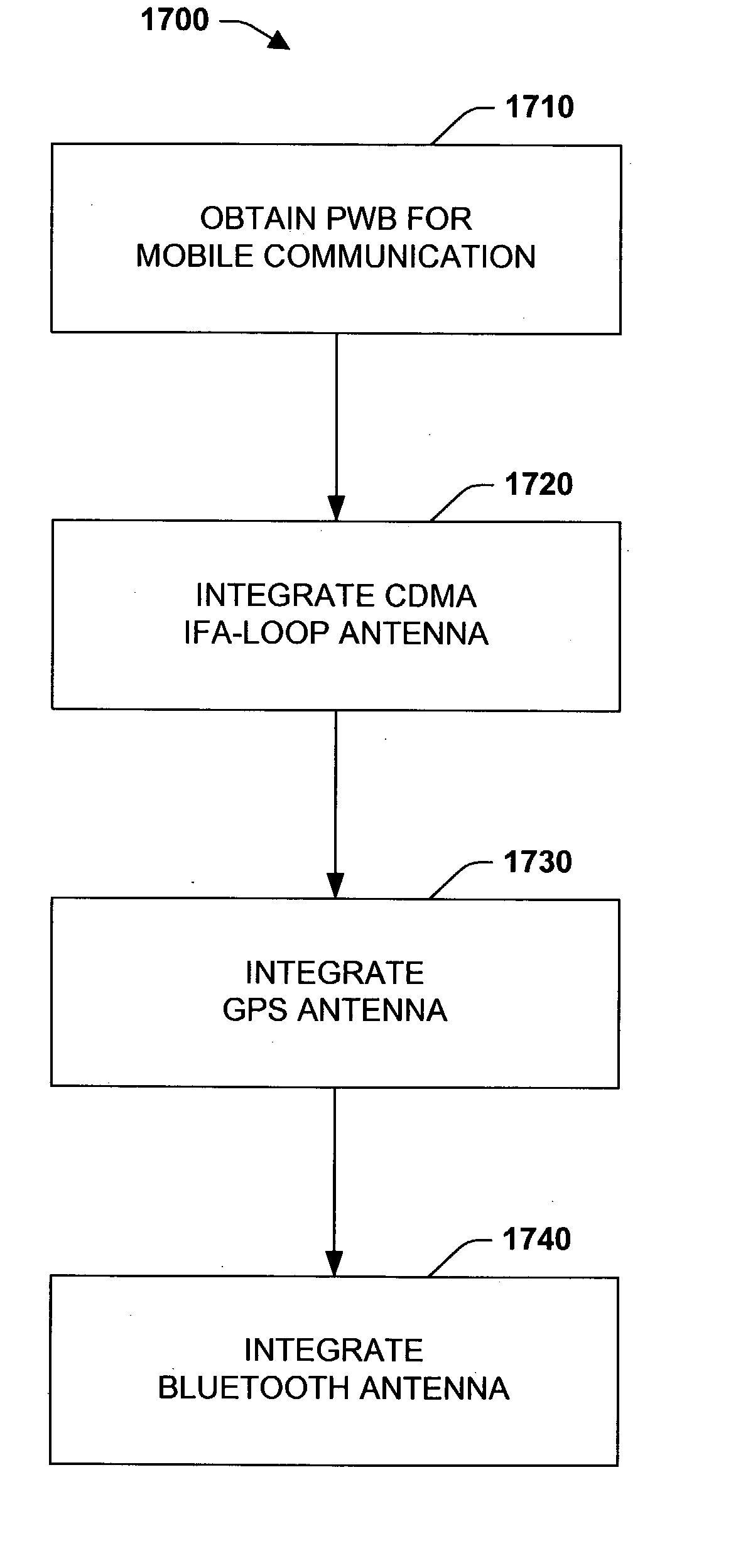
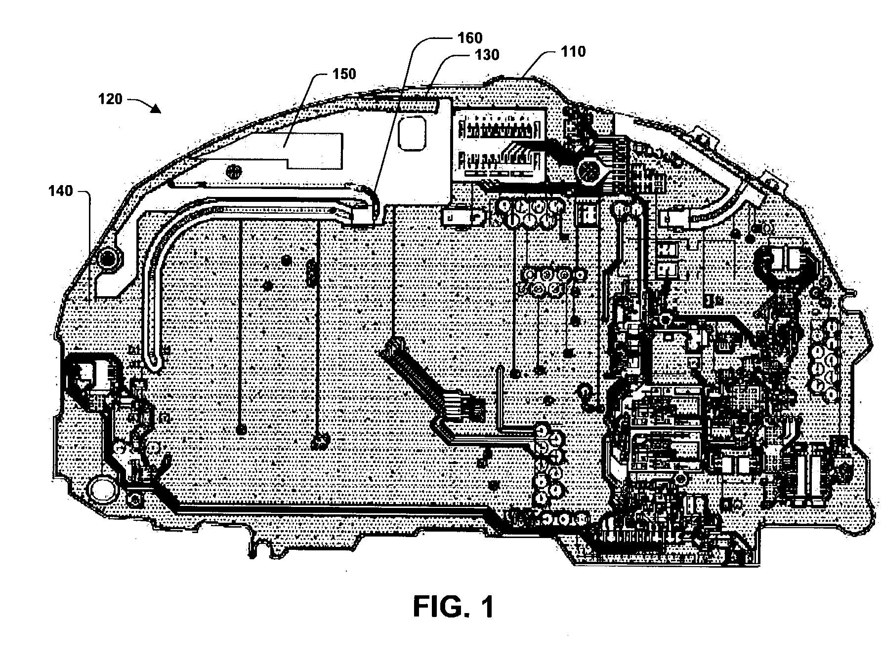
[0011] The present invention relates to systems and methods for a mobile communication device, such as a mobile terminal (for example a wireless telephone), that provides for cellular, PCS and GPS mobile communication, and information exchange with devices such as printers, computers, automobile audio systems and wireless headphones, for example. The present invention employs a novel and improved design comprising a dual band IFA / loop CDMA antenna for cellular and PCS communication, a GPS antenna for GPS communication and a Bluetooth antenna for information exchange with other devices employing Bluetooth technology. The present invention employs system and methods that reduce antenna and device size, cost, components and user hand interference, improves reception and reliability and efficiency.
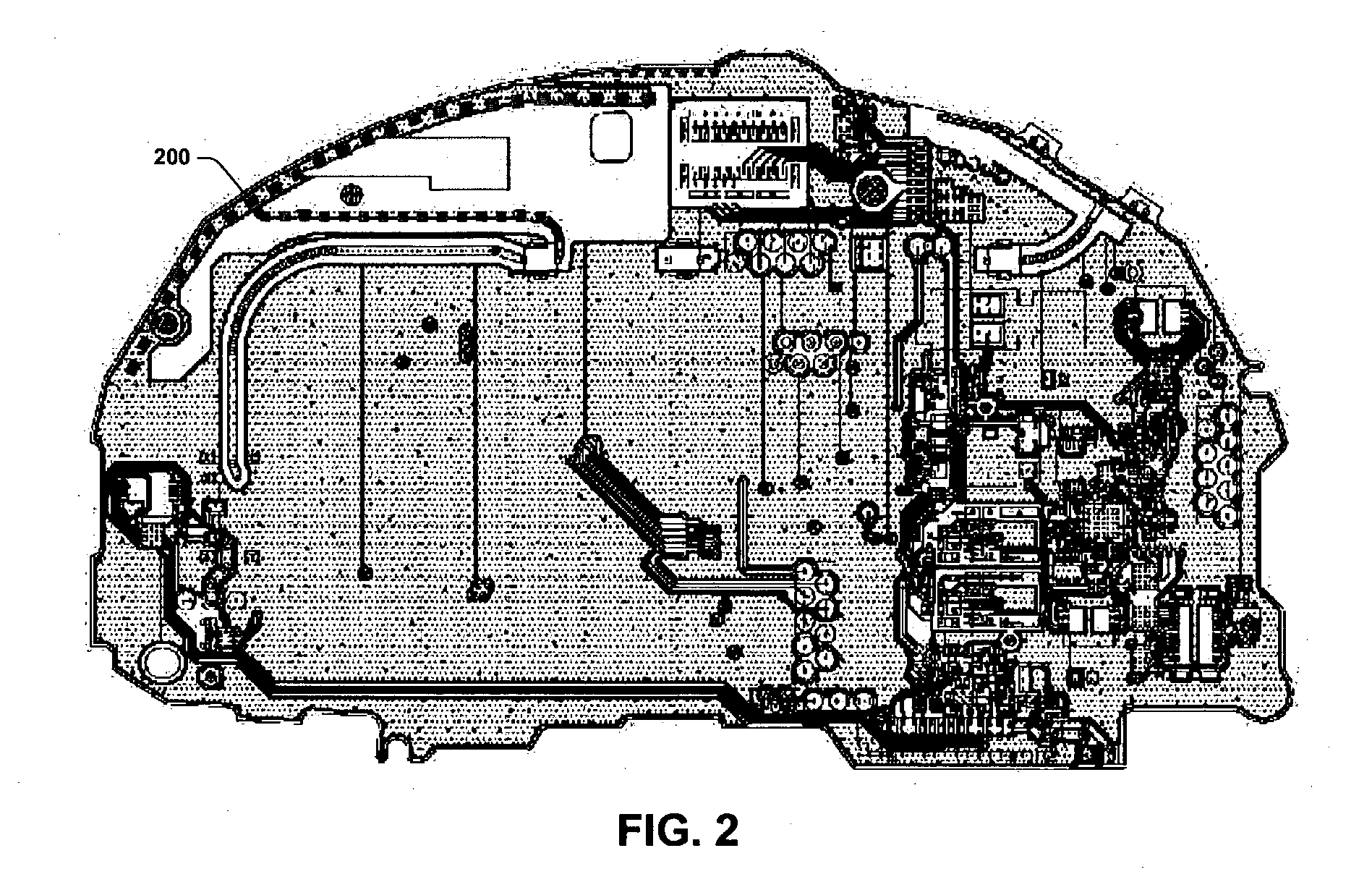
[0012] In one aspect of the present invention, a CDMA antenna can be fully integrated with a PWB to provide for dual banding, antenna compaction, reduction of components and cost, electromagnetic shielding, and improved performance. The CDMA antenna can comprise an IFA antenna and a loop antenna for dual banding. Conventional systems generally employ lumped elements for dual banding. Mitigating lumped elements can reduce footprint and cost via eliminating the lumped elements, and improve performance since lumped elements can be lossy.
[0013] The IFA antenna (e.g., quarter wavelength) can be configured to transmit and receive cellular information and the loop antenna (e.g., half wavelength) can be configured to transmit and receive PCS information. Configuring the IFA antenna generally comprises employing a capacitive tap. In general, one end of the tap is coupled to ground and the other end resides proximate and separated from the IFA antenna. The capacitive tap can additionally improve cell band peak gain and reduce interference from a user's hand. Conventionally, open-ended configurations are employed, which can lead to greater susceptibility to interference from a user's hand. The loop antenna can be configured via antenna loop size, which can be determined by the ground location, and an impedance matching stub.
[0014] In another aspect of the present invention, a GPS antenna and a firewall can additionally be integrated with the PWB to provide for GPS communication and mitigation of antenna coupling, respectively. The GPS antenna comprises at least a radiator, a carrier, mounting locations, a GPS Gamma match, a spring contact point and a spring contact. Generally the GPS antenna is partially integrated with the PWB, whereby the radiator, carrier and spring contact reside in an off-board assembly, which is coupled to the on-board GPS Gamma match and spring contact point. Additionally, the mounting locations facilitate coupling the off-board assembly on the PWB. The spring contact point provides a single connection point to facilitate IFA antenna construction. The single connection point reduces the number of connection points (which can improve reliability) typically employed by conventional systems. The firewall can be employed to mitigate coupling between the PCS antenna and the GPS antenna.

Problems solved by technology

Conventionally, open-ended configurations are employed, which can lead to greater susceptibility to interference from a user's hand.

Method used


Image

  • Systems and methods that employ a dualband IFA-loop CDMA antenna and a GPS antenna with a device for mobile communication
  • Systems and methods that employ a dualband IFA-loop CDMA antenna and a GPS antenna with a device for mobile communication
  • Systems and methods that employ a dualband IFA-loop CDMA antenna and a GPS antenna with a device for mobile communication

Examples


Embodiment Construction

[0053] The present invention is now described with reference to the drawings, wherein like reference numerals are used to refer to like elements throughout. In the following description, for purposes of explanation, numerous specific details are set forth in order to provide a thorough understanding of the present invention. It may be evident, however, that the present invention may be practiced without these specific details. In other instances, well-known structures and devices are shown in block diagram form in order to facilitate describing the present invention.

[0054] The present invention relates to systems and methods for mobile communication devices that provide cellular, PCS, GPS and / or Bluetooth communication. In general, the systems and methods employ a fully integrated dual band IFA / loop CDMA antenna for cellular and PCS communication, a GPS antenna for GPS communication, a Bluetooth antenna for information exchange with other devices employing Bluetooth technology, a f...


PUM


Abstract

The present invention comprises systems and methods for cellular, PCS, GPS and / or Bluetooth mobile communication (e.g., a mobile telephone). The systems and methods employ a fully integrated dual band IFA / loop CDMA antenna for cellular and PCS communication. Fully integrating the CDMA antenna within a PWB provides for mitigation of lumped elements to establish dual banding, and can provide for reduced antenna size, device size, cost and interference form a user's hand. The IFA antenna is configured to transmit and receive within the cellular frequency band via a capacitive tap, and the loop antenna is configured to transmit and receive within the PCS frequency band via an impedance matching stub and ground location. The system and methods further employ a firewall to mitigate antenna coupling, and a metal reflector to reduce the electromagnetic reflection, and improve antenna gain and efficiency.

Description

TECHNICAL FIELD [0001] The present invention generally relates to mobile communication devices, and more particularly, to a mobile communication device that employs a dual band IFA / loop CDMA antenna for cellular and PCS communication, a GPS antenna and a firewall to mitigate coupling between antennas. BACKGROUND OF THE INVENTION [0002] Early mobile communication devices employed analog radio transmission such as Advanced Mobile Phone System (AMPS), for example. Such analog technologies were sufficient for an emerging mobile communications consumer market. However, within a relatively short period of time, millions of new mobile communications subscribers, demanding more and more airtime, pushed the existing analog technology to a capacity limit or ceiling. As a consequence, dropped calls and busy signals became common, which fueled a demand for an improved mobile communication network. [0003] In response to the demand, industry developed digital wireless technologies that could acco...

Claims


Application Information

Patent Timeline
Patent Type & Authority Applications(United States)
IPC IPC(8): G01S1/00H01Q1/24H01Q1/52H01Q7/00H01Q9/42H01Q21/28H01Q21/30H04B7/216
CPCG01S19/36H01Q1/243H01Q1/521H01Q21/30H01Q9/42H01Q21/28H01Q7/00
Inventor HUI, PINGWONGTERGHEM, JARI VANEGGLESTON, STEVE
Owner NOKIA CORP
Learn More