Planar dual-frequency array antenna

a dual-frequency array and antenna technology, applied in the direction of individual energised antenna arrays, resonant antennas, independent non-interacting antenna combinations, etc., can solve the problems of mechanical pedestals not being able to serve the two antennas, common drawbacks of single frequency band operation, and additional drawbacks of all known antenna assemblies for mobile communication systems

Inactive Publication Date: 2000-09-19
SKYGATE INT TECH
View PDF3 Cites 85 Cited by
  • Summary
  • Abstract
  • Description
  • Claims
  • Application Information

AI Technical Summary

Problems solved by technology

All these known antenna assemblies for mobile communication systems suffer from the common drawback of operating in a single frequency band.
If the two-band service is provided through two different satellites, a mechanical pedestal cannot serve the two antennas.
Furthermore, the antennas of the first three groups mentioned above suffer from the additional drawback of having mechanical-tracking systems which tend to be cumbersome and slow, limited in their angular coverage, and which are not planar and have to protrude from the surface to which they are applied.
Thus, if such an antenna were to be mounted on a mobil

Method used


Image

  • Planar dual-frequency array antenna
  • Planar dual-frequency array antenna
  • Planar dual-frequency array antenna

Examples


Embodiment Construction

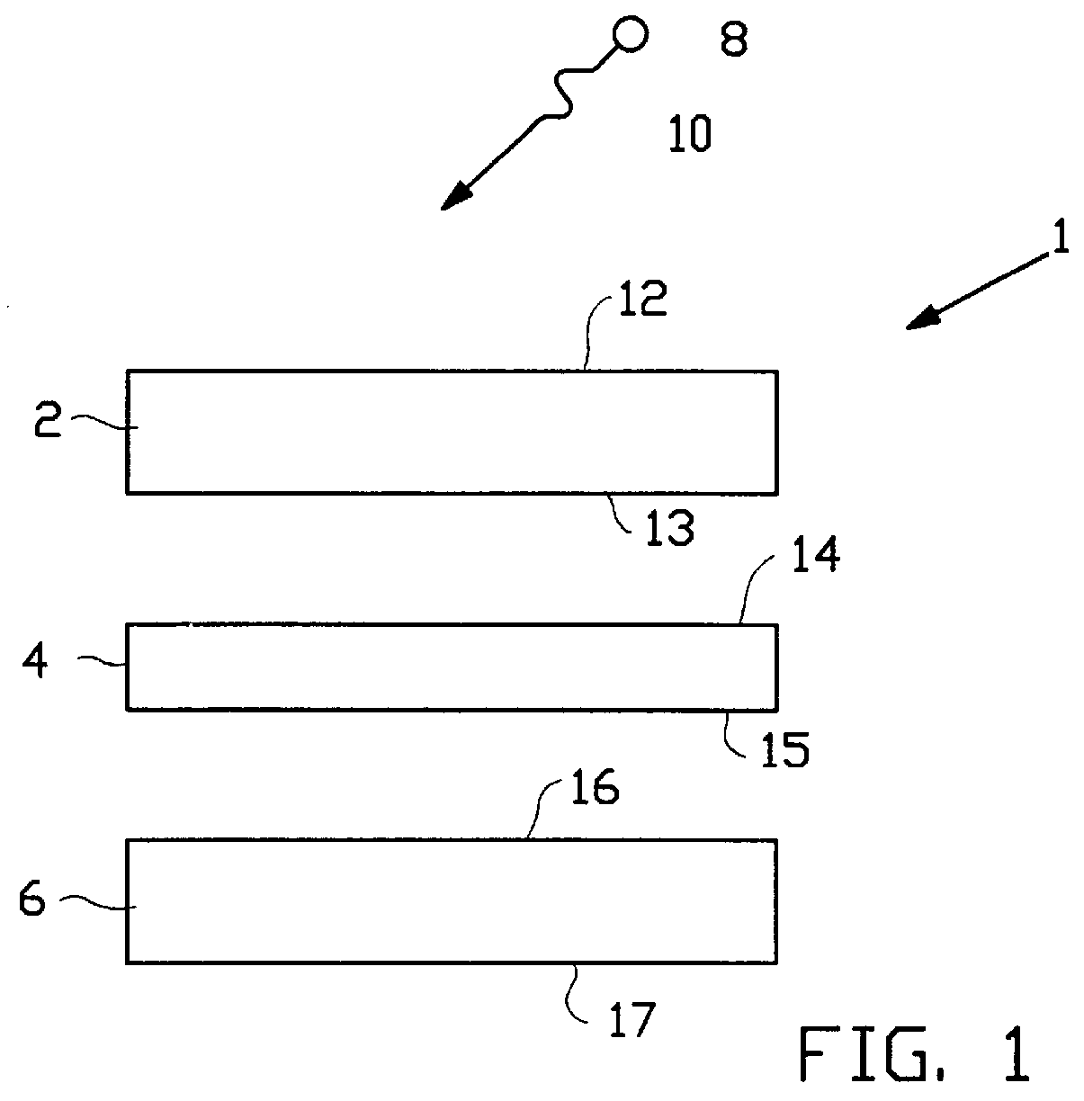
Attention is first drawn to FIG. 1 showing a schematic exploded side view of the planar antenna assembly 1 of the invention, which comprises three parts, a first planar array antenna unit 2, a dielectric plate 4 and a second planar array antenna unit 6. Also shown is an external source 8 of electromagnetic radiation 10. The "front face" and the "rear face" of any part of the planar antenna assembly, and of the planar antenna assembly itself, are defined relative to the external source 8. Hence, the front face 12 of the first planar array antenna unit 2 is that face orientated in the direction of the external source 8, whereas its rear face 13 is orientated in the opposite direction. Clearly then, electromagnetic radiation 10 incident on the first planar array antenna unit 2 from the external source 8 will be incident on the front face 12 and after passing through the first planar array antenna unit 2 it will exit from its rear face 13. Similarly, the dielectric plate has a front fac...


PUM


Abstract

PCT No. PCT/IL96/00037 Sec. 371 Date Jun. 11, 1999 Sec. 102(e) Date Jun. 11, 1999 PCT Filed Jul. 4, 1996 PCT Pub. No. WO98/01921 PCT Pub. Date Jan. 15, 1998A dual-frequency array antenna having an essentially planar structure with electronic beam steering capability in both a low and high frequency band independently of each other, constructed, in a layered formation, from a top planar array antenna unit operating in the low frequency band and a bottom planar array antenna unit operating in the high frequency band. The top planar array antenna is transparent to frequencies in the high frequency band.

Description

The present invention relates to planar antenna assemblies for use in radiowave communications in general and in mobile satellite communication systems in particular.PRIOR ARTThe following is a list of references which are believed to be pertinent to the present invention:Andrasic G. and James J. R. (1987). "Investigation of Superimposed Dichroic Microstrip Antennas," 5th International Conference on Antenna and Propagation, ICAP 87, pp. 485-488, March-April, York, UK.Andrasic G. and James J. R. (1988). "Microstrip Window Array," Electronic Letters, Vol. 24, No. 2, pp 96-97.Hiroyuki Inafuku, et al. (1989) "Mobile Receiving Antenna System of Direct Broadcast Systems for Train Applications," International Symposium of Antennas and Propagation, Tokyo, Japan, August.Lee S. W., et al. (1982). "Simple Formulas for Transmission Through Periodic Metal Grids or Plates," IEEE Transactions and Antennas and Propagation, Vol. AP-30, pp. 904-909.U.S. Pat. No. 5,043,738U.S. Pat. No. 5,262,791The ab...

Claims


Application Information

Patent Timeline
IPC IPC(8): H01Q5/00H01QH01Q1/38H01Q3/26H01Q5/42H01Q15/00H01Q21/06H01Q21/28H01Q21/30
CPCH01Q21/065H01Q5/42H01Q15/006
Inventor LEVI, SHEM-TOV
Owner SKYGATE INT TECH
Why Eureka
Try Eureka