System for autonomous vehicle navigation with carrier phase DGPS and laser-scanner augmentation

a technology of laser scanning and autonomous vehicle, applied in the field of navigation systems, can solve problems such as performance degradation

Active Publication Date: 2006-05-18
AUTO TECH GRP LLC
View PDF7 Cites 82 Cited by
  • Summary
  • Abstract
  • Description
  • Claims
  • Application Information

AI Technical Summary

Problems solved by technology

Developing an outdoor navigation system that enables a vehicle to go through many obstacles is a major challenge for autonomous ground vehicles

Method used


Image

  • System for autonomous vehicle navigation with carrier phase DGPS and laser-scanner augmentation
  • System for autonomous vehicle navigation with carrier phase DGPS and laser-scanner augmentation
  • System for autonomous vehicle navigation with carrier phase DGPS and laser-scanner augmentation

Examples


Embodiment Construction

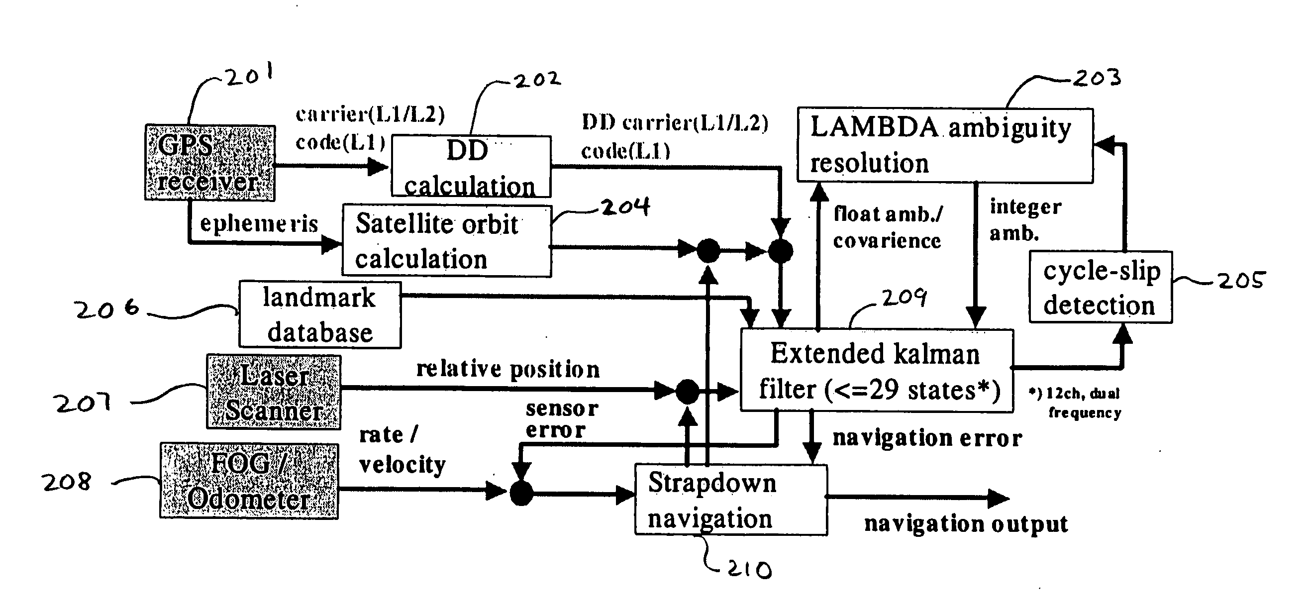
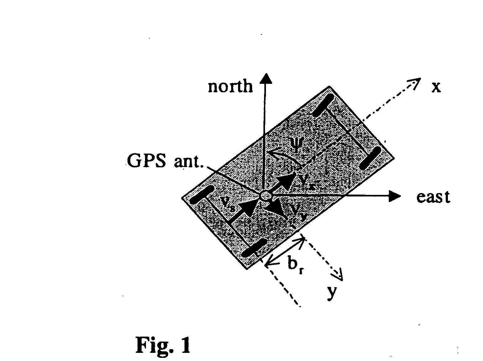
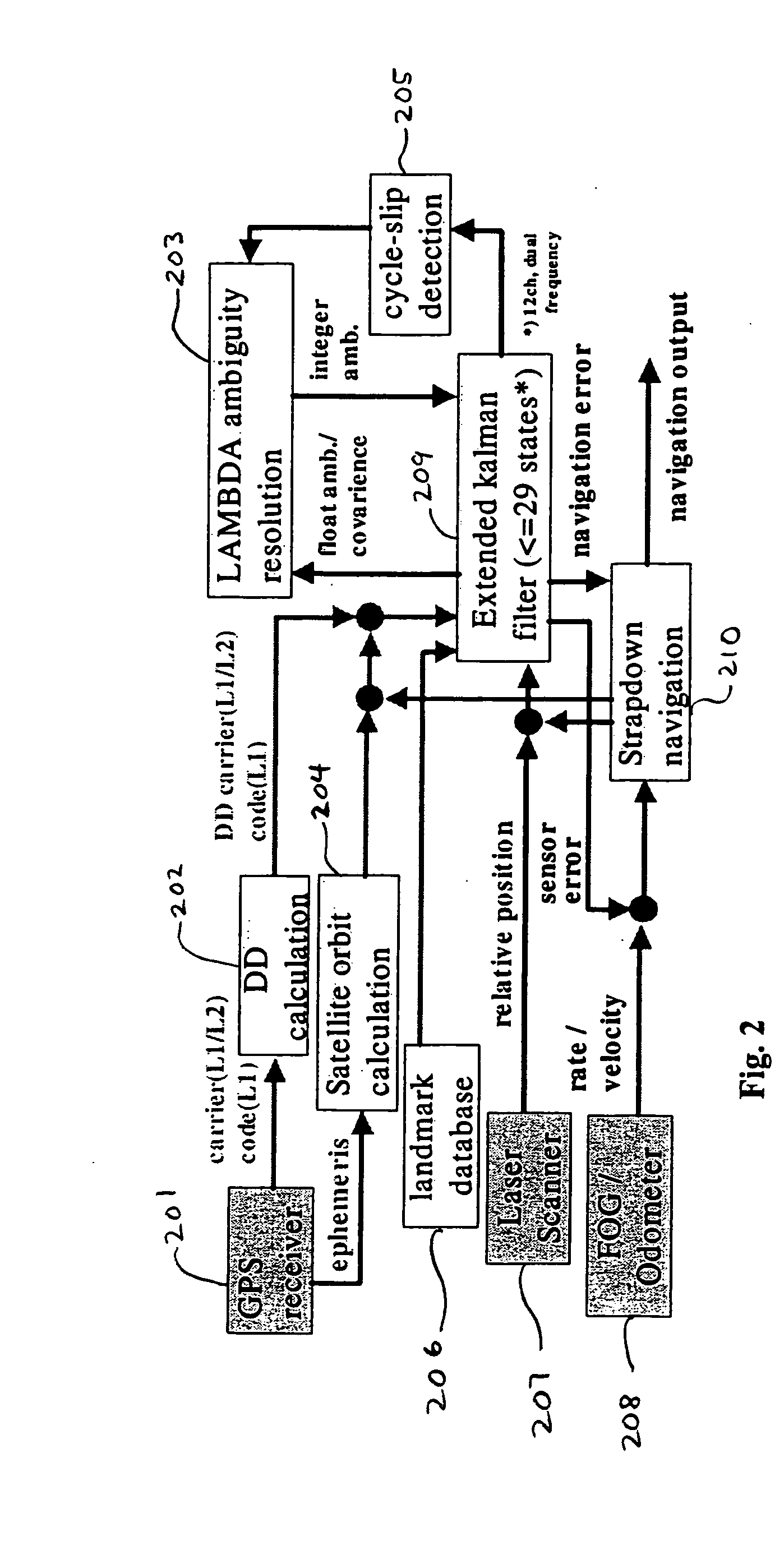
[0040] The navigation system consists of horizontal strapdown navigation calculation and the extended Kalman filter (EKF). FIG. 1 shows a horizontal dynamics model of the vehicle. The strapdown calculation in a local horizontal frame is performed by position and heading (yaw angle) updates using rate gyro, e.g., a low-cost Fiber Optic Gyro (FOG), and the odometer input compensated by the EKF. A Micro Electro Mechanical Systems (MEMS) gyro and a vibrating gyro may also be used. The position of the vehicle is defined as the phase center of a GPS antenna, and the position dynamics in local NED (North-East-Down) frame is defined as follows, [ ⁢N. ⁢E.]=R⁡(ψ)⁡[vxvy];D.=0(1)R⁡(ψ)=[cos⁢ ⁢ψ-sin⁢ ⁢ψsin⁢ ⁢ψcos⁢ ⁢ψ](2)

where vx and vy are the body-frame velocity defined as follows, [vxvy]=[Vsbr⁢rs].(3)

Vs and rs are the compensated velocity measured by the odometer and the yaw rate measured by FOG, respectively. br is the horizontal distance between the rear wheel axis and the GPS antenna pha...


PUM


Abstract

A horizontal navigation system aided by a carrier phase differential Global Positioning System (GPS) receiver and a Laser-Scanner (LS) for an Autonomous Ground Vehicle (AGV). The high accuracy vehicle navigation system is highly demanded for advanced AGVs. Although high positioning accuracy is achievable by a high performance RTK-GPS receiver, the performance should be considerably degraded in a high-blockage environment due to tall buildings and other obstacles. The present navigation system is to provide decimetre-level positioning accuracy in such a severe environment for precise GPS positioning. The horizontal navigation system is composed of a low cost Fiber Optic Gyro (FOG) and a precise odometer. The navigation errors are estimated using a tightly coupled Extended Kalman Filter (EKF). The measurements of the EKF are double differenced code and carrier phase from a dual frequency GPS receiver and relative positions derived from laser scanner measurements.

Description

BACKGROUND OF THE INVENTION FIELD OF THE INVENTION [0001] The present invention relates generally to navigational systems using inertial and satellite-based navigation. [0002] The present invention includes the use of various technologies referenced and described in the documents identified in the following LIST OF REFERENCES, which are cited throughout the specification by the corresponding reference number in brackets: LIST OF REFERENCES [0003] [1] Paul de Jonge and Christian Tiberius. The LAMBDA method for integer ambiguity estimation: implementation aspects. LGR-Series 12, Delft University of Technology, August 1996. [0004] [2] Rui Hirokawa, Koichi Sato, and Kenji Nakakuki. Design and evaluation of a tightly coupled GPS / INS using low cost MEMS IMU. In GNSS Symposium 2003, Tokyo, Japan, November 2003. [0005] [3] Tetsuro Imakiiere, Yuki Hatanaka, Yohta Kumaki, and Atsusi Yamagiwa. Geonet: Nationwide GPS array of Japan. GIS development, 8(3), March 2004. [0006] [4] J. Takiguchi and...

Claims


Application Information

Patent Timeline
IPC IPC(8): G01C21/00G01S19/48G01S19/05G01S19/11G01S19/21G01S19/29G01S19/46
CPCG01C21/165G01S19/44G05D1/024G05D1/027G05D1/0272G05D1/0278G01C21/1652
Inventor HIROKAWA, RUI
Owner AUTO TECH GRP LLC
Why Eureka
Try Eureka