Jiggle measuring system and jiggle measuring method

a technology of jiggle measurement and measurement method, which is applied in the field of camera shake measurement system, can solve the problems of not being able to detect and correct camera shake around the roll axis, and being difficult to observe time-series changes of camera shake direction and amount,

Inactive Publication Date: 2010-01-21
UNIVERSITY OF ELECTRO-COMMUNICATIONS
View PDF3 Cites 21 Cited by
  • Summary
  • Abstract
  • Description
  • Claims
  • Application Information

AI Technical Summary

Benefits of technology

[0017]The present invention has been made in view of the above conventional conditions and an object thereof is to provide a camera shake measurement system and a method for measuring camera shakes that make it possible to detect camera shake variations of a photographing apparatus without installing an additional device on an optional photographing apparatus and can further detect camera shakes around the three axes of the photographing apparatus.

Problems solved by technology

So the evaluation is distant because it is difficult to apply the invention to camera shake measurement of an optional digital camera.
Moreover, in the above case, detectable camera shake directions are limited depending on the direction in which a gyro sensor is installed, and it is further difficult to observe time-series changes of a camera shake direction and a camera shake amount.
The camera shake correction functions of typical commercially-available digital cameras detected and corrected only the camera shake amounts around the pitch axis and pan axis but did not detect and correct camera shakes around the roll axis (light axis) (for example, see FIG. 9 in Japanese Patent No. 3143527).
It is difficult to detect triaxial rotational movement that is an actual camera shake phenomenon.

Method used


Image

  • Jiggle measuring system and jiggle measuring method
  • Jiggle measuring system and jiggle measuring method
  • Jiggle measuring system and jiggle measuring method

Examples


Embodiment Construction

[0067]Embodiments of the present invention will be described below with reference to the drawings.

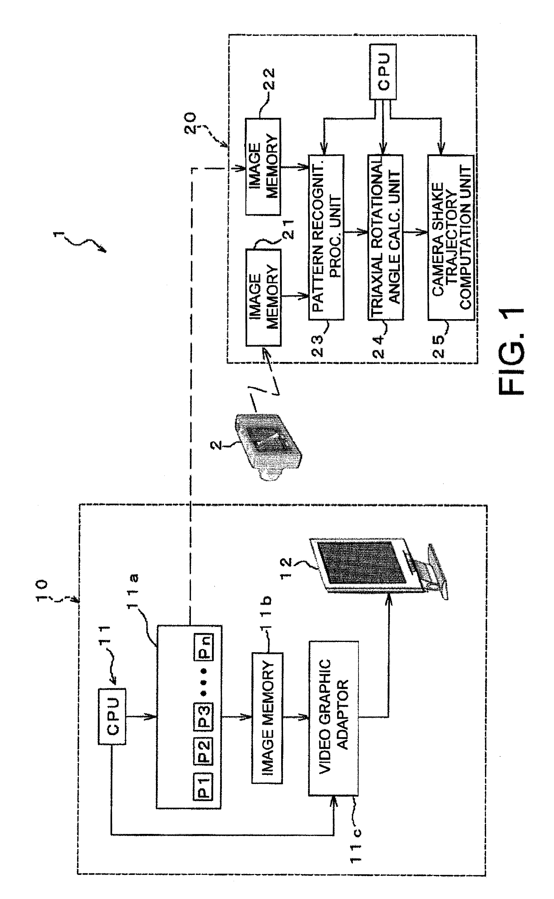
[0068]FIG. 1 is a block diagram showing one example of a camera shake measurement system according to the present invention.

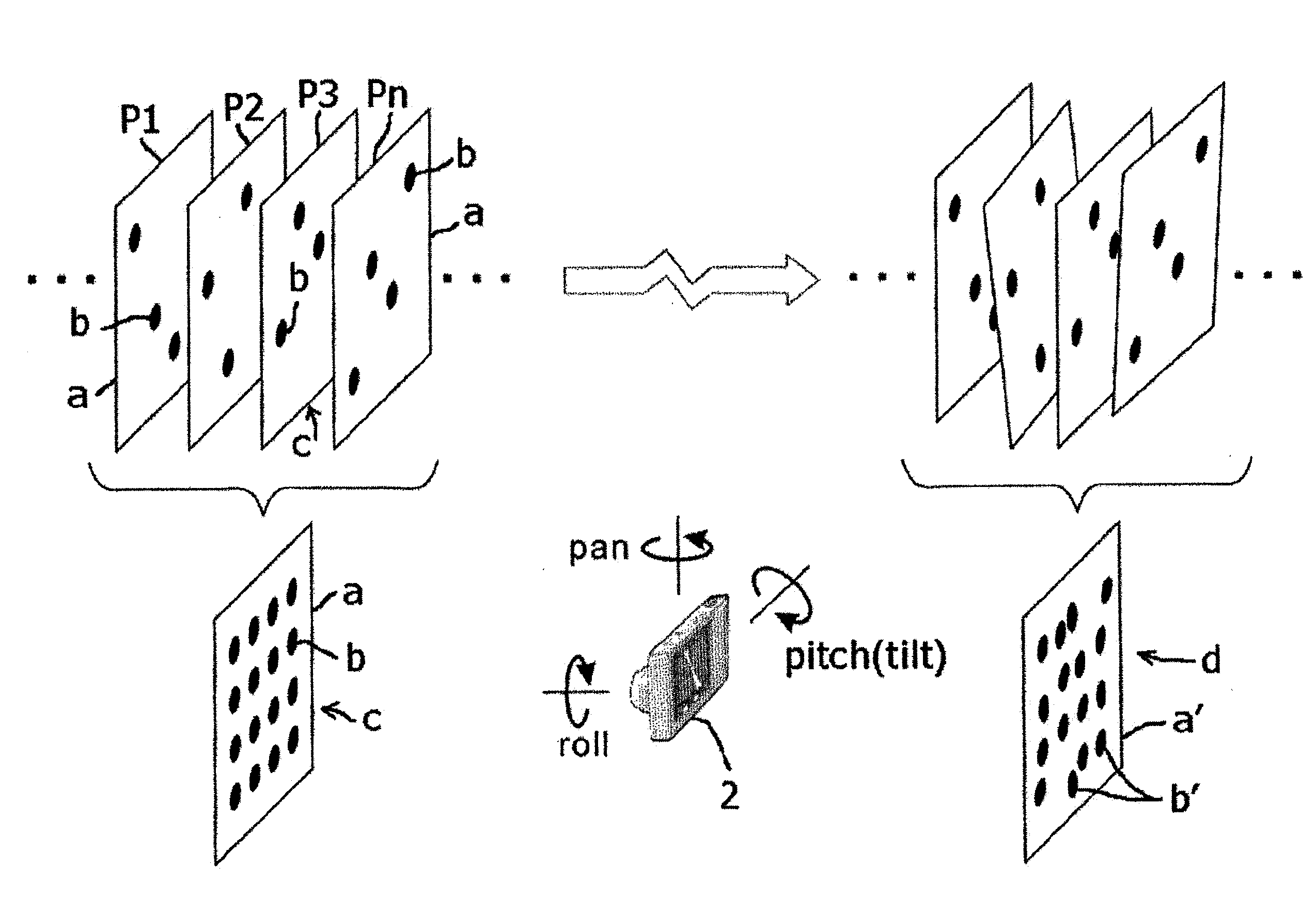
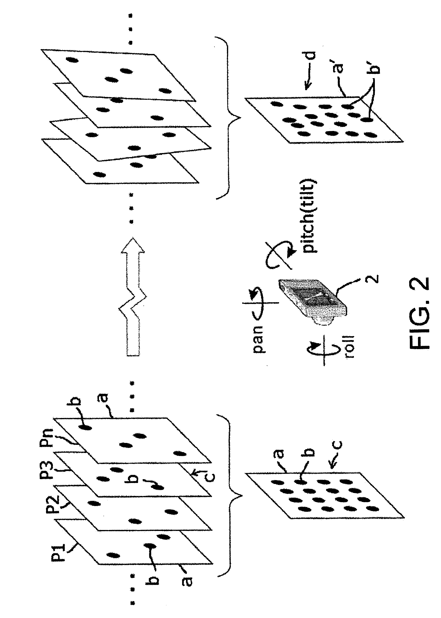
[0069]The camera shake measurement system 1 comprises a test pattern display unit 10 (display means) which sequentially displays a plurality of test patterns P1 to Pn different in kind and an arithmetic processing unit 20 which pattern-recognizes an images that match each of the test patterns P1 to Pn from a composite image d (see FIG. 2 and FIG. 3) produced by photographing at least two test patterns of the test patterns P1 to Pn by a photographing apparatus 2 as still images and detects a relative moving amount for each moving direction of each of the test patterns when the pattern recognition is performed.

[0070]The test pattern display unit 10 comprises a general computer 11 equipped with a CPU, a storage device, an input / output device, and the like, a program f...


PUM


Abstract

A camera shake measurement system includes a display unit for sequentially displaying a plurality of distinguishable test patterns, a first storage unit for storing as a template each of the plurality of test patterns to be displayed, a second storage unit for storing a composite image produced by photographing at least two test patterns as still images from the plurality of test patterns to be sequentially displayed by a photographing apparatus, and a pattern recognition unit for recognizing images that match each of the templates from the composite image by calling the templates from the first storage unit, calling the composite image from the second storage unit, and moving, for each of the called templates, the template while superposing the template on the composite image.

Description

TECHNICAL FIELD OF THE INVENTION[0001]The present invention relates to a camera shake measurement system that measures camera shakes of photographing apparatuses such as a digital camera and other optical apparatuses and a method for measuring camera shakes.BACKGROUND OF THE INVENTION[0002]Camera shake correction apparatuses provided in conventional digital cameras calculate a camera shake amount by integrating acceleration detected by a gyro sensor and displaces a lens, an apex-angle prism, an image device, or the like, so as to compensate this camera shake amount.[0003]The invention disclosed in Japanese Patent No. 3143527, as one example of such camera shake correction apparatuses, comprises apex-angle sensors (43, 44 (gyro sensor, or the like)) that detect camera shakes, a variable apex-angle prism (41) that is deformable to change a light axis, actuators (48, 49) that deform the variable apex-angle prism (41), a control circuit that applies driving voltage to the actuator, and ...

Claims


Application Information

Patent Timeline
Patent Type & Authority Applications(United States)
IPC IPC(8): G03B17/00
CPCG03B5/00H04N5/23248H04N5/145G03B2217/005H04N23/68H04N17/002
Inventor NISHI, KAZUKIOITA, MASAYAMASAKI, YASUO
Owner UNIVERSITY OF ELECTRO-COMMUNICATIONS
Why Eureka
Try Eureka