Lubricant applicator and image forming apparatus including same

a technology of lubricant applicator and image forming apparatus, which is applied in the direction of manual lubrication, instruments, machines/engines, etc., can solve the problems of kneading pulverization method, difficult to produce small-diameter spherical toner particles, and complicated cleaning of photoreceptors after cleaning

Inactive Publication Date: 2010-01-28
RICOH KK
View PDF11 Cites 29 Cited by
  • Summary
  • Abstract
  • Description
  • Claims
  • Application Information

AI Technical Summary

Problems solved by technology

One problem, however, is that it is difficult to produce small-diameter spherical toner particles with a known kneading pulverization method.
Although advantageous, such small-diameter spherical toner has a drawback in that it complicates cleaning of a photoreceptor after an image forming operation, as the following discussion explains.
However, use of small-diameter spherical toner makes it difficult to remove the toner with the cleaning blade because the cleaning blade removes the toner and the like while slidably contacting the surface of the photoreceptor.
This sliding contact or scraping action causes deformation of an edge portion of the cleaning blade due to friction resistance with the photoreceptor, and can result in breaking the contact between the blade and the photoreceptor, thereby undesirably forming a gap between the photoreceptor and the cleaning blade.
If the amount of toner slips from the cleaning blade is large enough, it can cause abnormal imaging including fogging, etc.
When such filming occurs, an abnormal image is formed, in which, for example, a solid portion of an image may include white spots.
However, in a case in which an image having a relatively high image area ratio is printed continuously, when a large amount of toner adheres to the lubricant application brush, the lubricant sticks to the toner on the brush, thereby preventing the lubricant from being supplied to the surface of the photoreceptor even if the lubricant application brush frictionally contacts the lubricant.
However, in order to apply the lubricant, a smoothing member is necessary, thereby complicating efforts to reduce the size and the cost of the image forming apparatus.
However, with this configuration the toner remains on the application brush, preventing the lubricant from being applied effectively to the photoreceptor.
As a result, upon maintenance, such powder lubricant scatters and falls off.
Depending on the amount of accumulation, the amount of pressure of the cleaning blade pressing the image bearing member changes undesirably, causing degradation of cleaning performance.
However, the flicker member is insufficient because, after the toner is removed from the brush by flicking, the toner sticks again to the brush due to airflow.
As a result, the brush roller 203a cannot adequately supply the lubricant to the surface of the photoreceptor.

Method used


Image

  • Lubricant applicator and image forming apparatus including same
  • Lubricant applicator and image forming apparatus including same
  • Lubricant applicator and image forming apparatus including same

Examples


embodiment 1

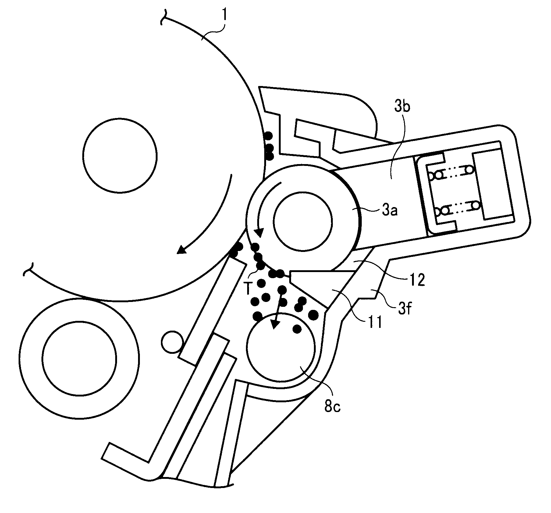
[0076]Referring now to FIG. 5, there is provided a cross-sectional view illustrating the lubricant applicator according to the illustrative embodiment of the present invention.

[0077]According to the present embodiment, substantially below the brush roller 3a, a triangular flicker 11 is provided. The base portion of the flicker 11 is attached to a housing 3f of the lubricant applicator 3. The tip portion as well as the upper surface of the flicker 11 contact the brush roller 3a. With this configuration, the brush 3a, the flicker 11, and the solid lubricant 3b define a sealed space 12 therebetween. Therefore, the toner T removed from the brush roller 3a by the flicker 11, indicated by dots in FIG. 5, is prevented from sticking again to the brush roller 3a due to airflow and the like. The brush roller 3a is always free from the toner T by the flicker 11 and can reliably scrape and supply the solid lubricant 3b to the photoreceptor drum 1.

[0078]The flicker 11 of the present embodiment s...

embodiment 2

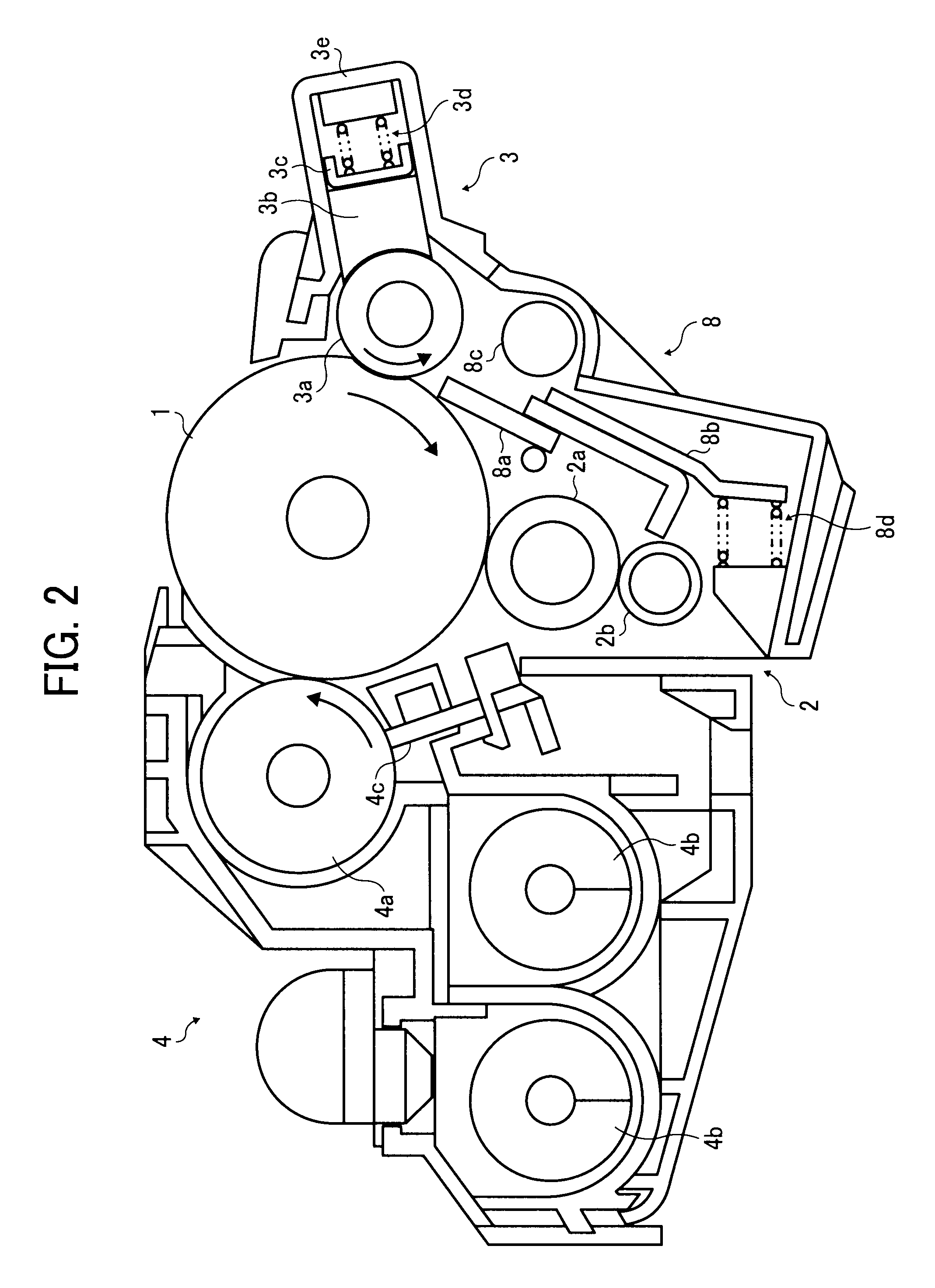
[0091]Referring now to FIG. 10, there is provided a partially enlarged view of the vicinity of the photoreceptor drum 1 of one example of an image forming apparatus using a direct transfer method.

[0092]In FIG. 10, the charging device 2, the lubricant applicator 3, the cleaning device 8, a transfer roller 6, and so forth are disposed around the photoreceptor drum 1.

[0093]The recording medium P is transported from the left to the right in FIG. 10 between the photoreceptor drum 1 and the transfer roller 6. The toner image on the photoreceptor drum 1 is transferred onto the recording medium.

[0094]The lubricant applicator 3 includes the lubricant application roller 3a, the solid lubricant 3b, a pressure member 3d, the application blade 3g, a support member 3h, and so forth.

[0095]The solid lubricant 3b is pressed against the application roller 3a (brush roller), serving as the lubricant application member. As the brush roller 3a rotates, the brush roller 3a scrapes the solid lubricant, th...


PUM


Abstract

A lubricant applicator includes a solid mold lubricant, a lubricant application roller, and a flicker member. The lubricant application roller scrapes and applies the lubricant to an image bearing member. The flicker member removes a powder substance adhered to the surface of the lubricant application roller and is disposed upstream of the solid mold lubricant in a direction of rotation of the lubricant application roller. The lubricant application roller, the flicker member, and the solid mold lubricant define a sealed space therebetween. A lubricant applicator includes the solid mold lubricant, the lubricant application roller, the flicker member, and an adherence prevention member that prevents the substance removed by the flicker member from adhering again to the lubricant application roller. A lubricant applicator includes the solid mold lubricant, the lubricant application roller, and a lubricant receiver that receives the scraped lubricant from the lubricant application roller.

Description

CROSS-REFERENCE TO RELATED APPLICATIONS[0001]This patent application is based on and claims priority pursuant to 35 U.S.C. §119 from Japanese Patent Application No. 2008-262766, filed on Oct. 9, 2007 in the Japan Patent Office, which is hereby incorporated herein by reference in its entirety.BACKGROUND OF THE INVENTION[0002]1. Field of the Invention[0003]Exemplary aspects of the present invention generally relate to a lubricant applicator, a process cartridge including the lubricant applicator, and an image forming apparatus including same.[0004]2. Description of the Background Art[0005]With image forming apparatuses such as copiers, printers, facsimile machines and the like, there is increasing market demand for high-quality imaging. In particular, in order to obtain high-resolution color images, efforts to reduce a diameter of particles of toner used to form images and make the toner particles more spherical are being pursued.[0006]Toner particles of substantially small diameter e...

Claims


Application Information

Patent Timeline
Patent Type & Authority Applications(United States)
IPC IPC(8): G03G21/00F16N7/14
CPCF16N7/24
Inventor HONJOH, KENJISATOH, TOSHIYANAGASHIMA, HIROYUKIITOH, FUMIHITOONO, HIROSHIAMEMIYA, KENSHAKUTO, MASAHIKOKOIKE, TOSHIOARAI, YUJIKUWABARA, NOBUOOKAMOTO, MICHIYA
Owner RICOH KK
Why Eureka
Try Eureka