High Security Cylinder Lock

a high-security, cylinder lock technology, applied in the field of cylinder locks, can solve the problem that the basic disadvantage of easily being picked open has not changed theoretically, and achieve the effect of general cost-effective manufacturing, easy assembly, and easy maintenan

Inactive Publication Date: 2010-02-04
XU FORREST +1
View PDF0 Cites 7 Cited by
  • Summary
  • Abstract
  • Description
  • Claims
  • Application Information

AI Technical Summary

Benefits of technology

[0007]It is another related object of the present invention to provide a cylinder pin tumbler lock that is generally cost efficient to manufacture.
[0008]It is a further related object of the present invention to provide a cylinder pin tumbler lock that is easy to be assembled, mastered and serviced.
[0010]The main difference between the cylinder lock of the present invention with the cylinder lock in prior art is the initial-on-duty pin. Almost all the cylinder lock in the prior art use its driver pins as its initial-on-duty pins which span the plug from rotating within the lock housing while the combination pins or pin sub-assemblies are normally exposed to the opening keyway. This pin-configuration makes lock picking or bumping practically or theoretically easy. The cylinder lock of the present invention uses the combination pins as the initial-on-duty pins and isolates these pins from the opening keyway. Each combination pin's position is not controlled directly by the key profile and the driver spring as it is in the prior art, but by the compound force of its corresponding balancing spring and driver spring. The extension force of the balancing spring at its initial pre-loaded length within the balancing pin bore is greater than the extension force of its corresponding driver spring at its initial fully loaded length within the driver pin bore. The key profile can only touch the balancing pins and move them to such new positions that the top end of all combination pins being just tangent to the outer cylindrical surface of the plug, or as we say the share line of the locking mechanism. By those new approaches, the cylinder lock of the present invention makes it impossible to unlock the lock by means of conventional lock picking or bumping technologies.

Problems solved by technology

So its basic disadvantage of easily being picked open has not changed theoretically.

Method used


Image

  • High Security Cylinder Lock
  • High Security Cylinder Lock
  • High Security Cylinder Lock

Examples


Embodiment Construction

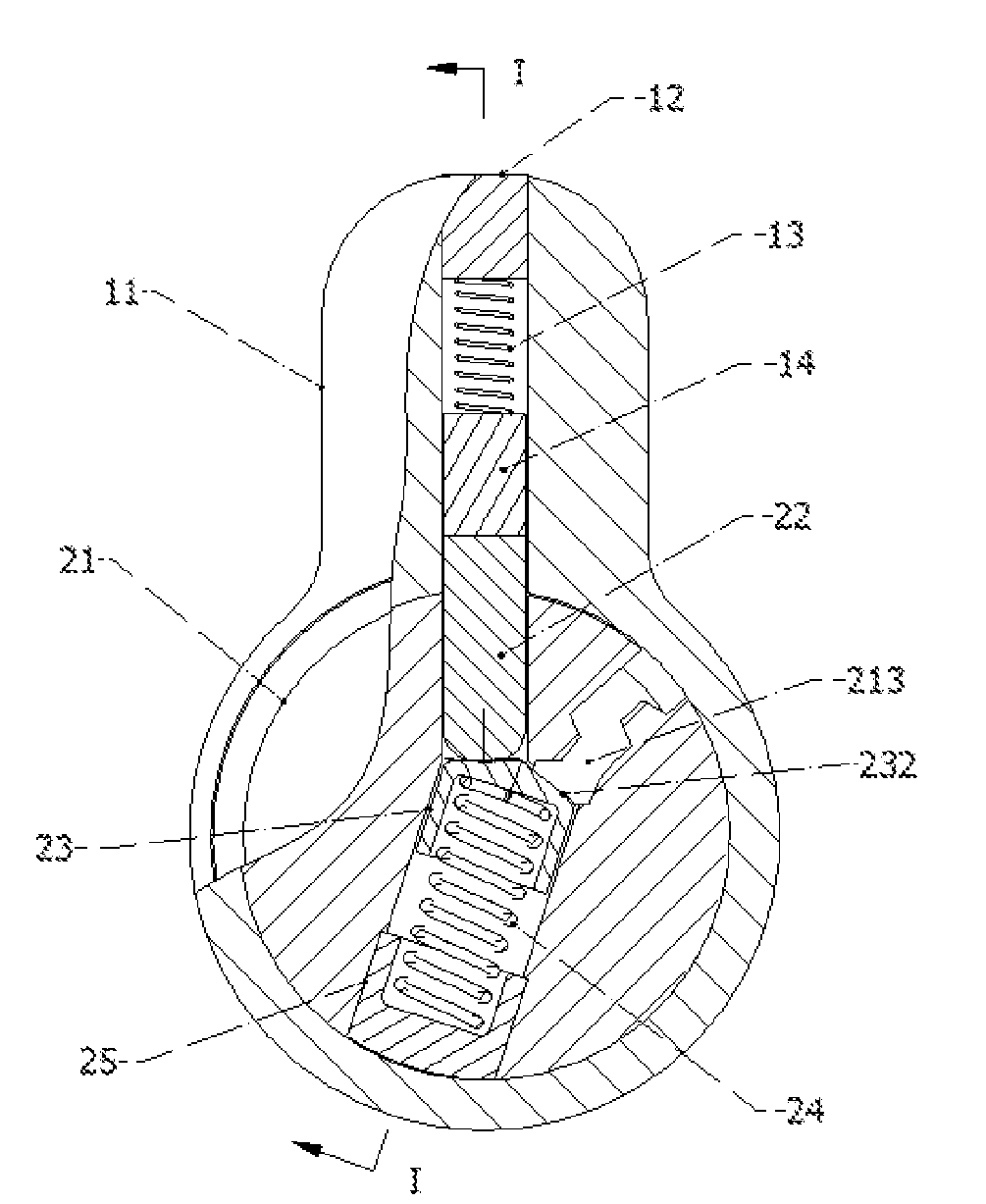
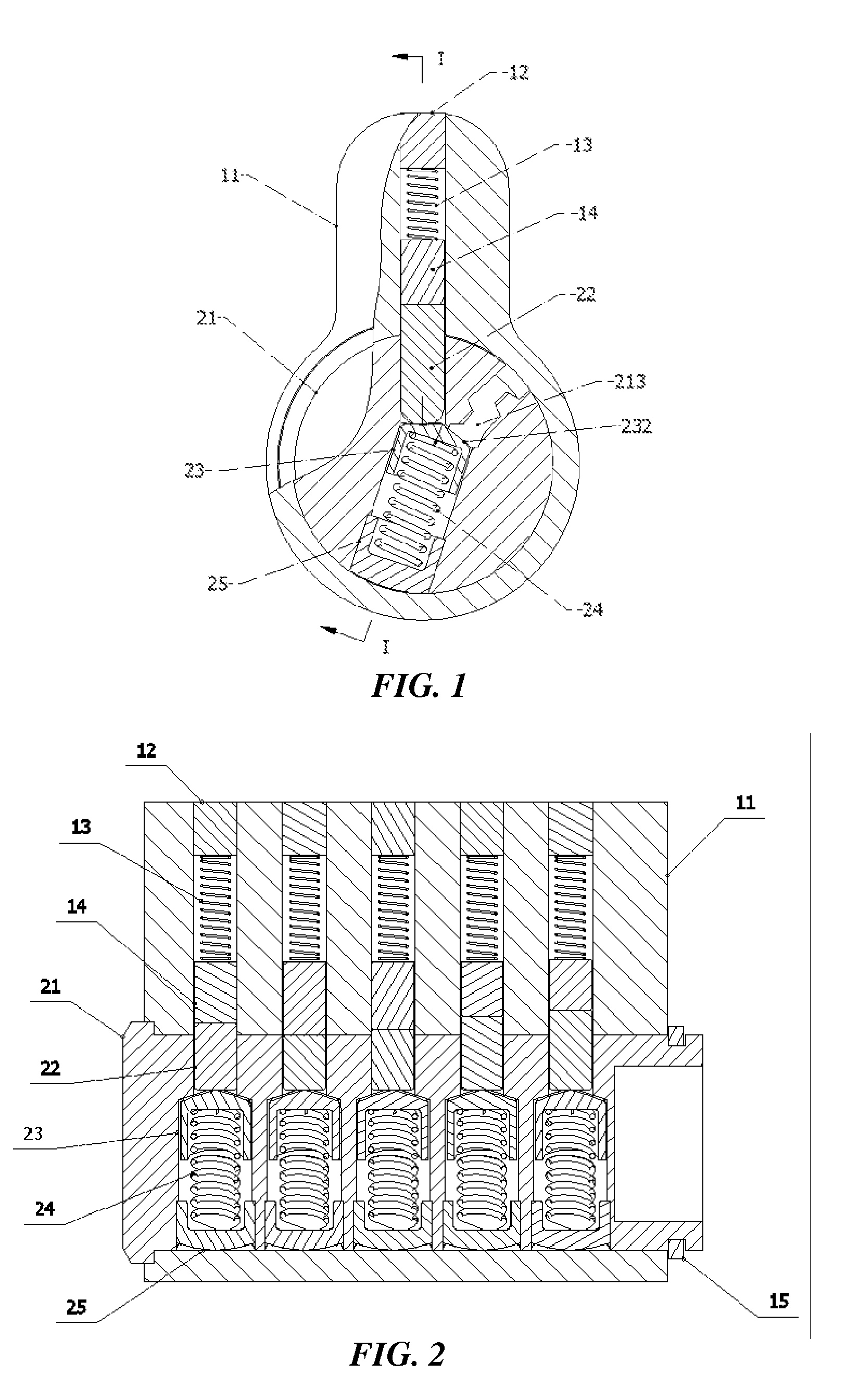
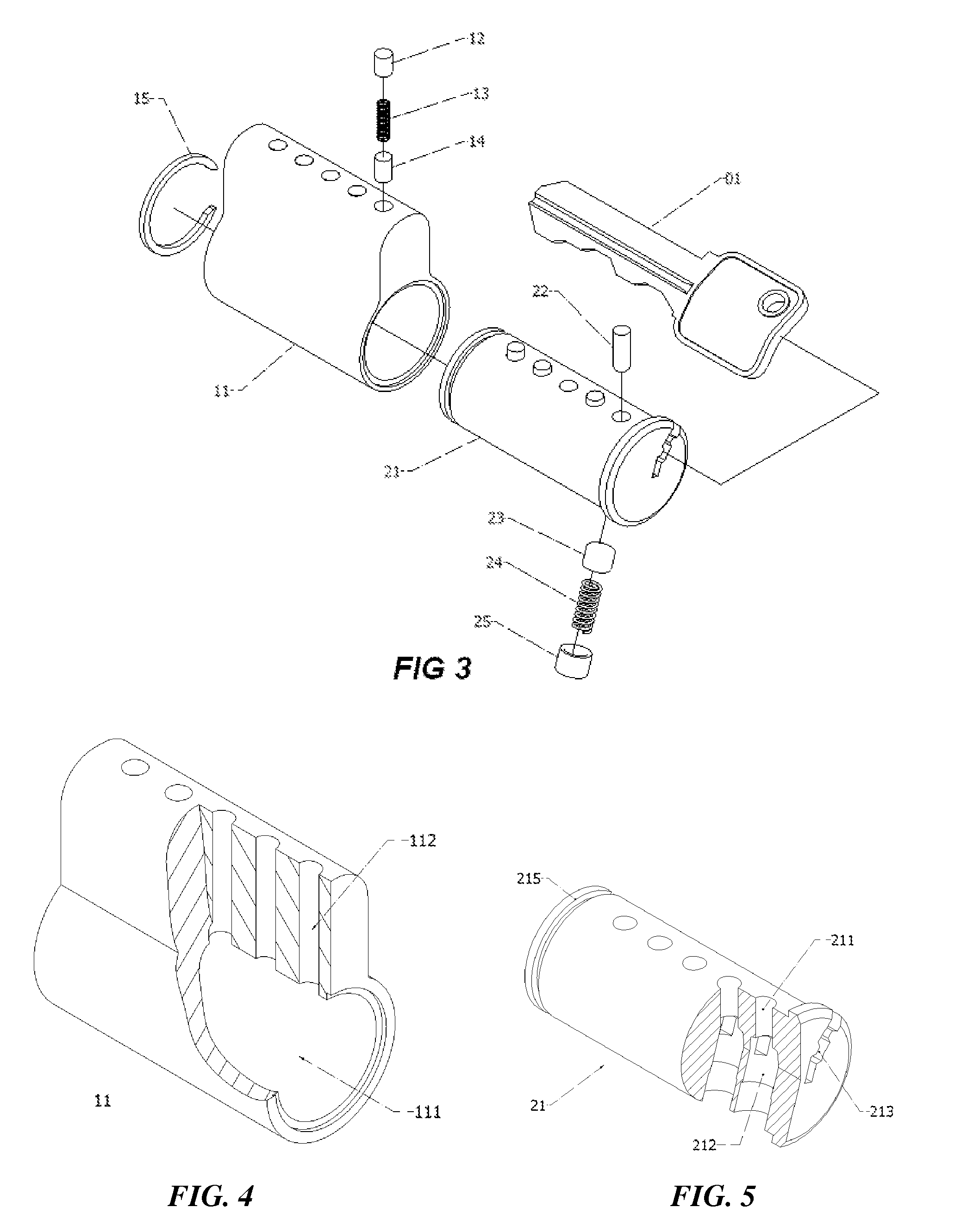
[0026]With reference to FIG. 1, FIG. 2 and FIG. 3, a first preferred embodiment of an exemplary high security cylinder lock in accordance with the present invention comprises a housing 11, a plurality of driver pins 14, coiled compression driver springs 13 and driver pin bore seals 12; a plug 21 rotatable within the housing 11 by means of a key (not shown) as known in the art, a plurality of combination pins 22; a plurality of spring balancing pins 23, coiled compression balancing springs 24, and balancing pin bore seals 25.

[0027]With reference to FIG. 2 and FIG. 4, the housing 11 comprises a through bore 111 and a plurality of driver pin bores 112 which are communicating with the through bore 111 and outer peripheral surface.

[0028]Slidably disposed into each driver pin bore 112 are a driver pin 14 and a coiled compression driver spring 13. The driver pin bores 112 are fixedly sealed with driver pin bore seals 12. The driver pin bores 112 may also be sealed by a seal strip (not show...


PUM


Abstract

A high security cylinder lock includes a housing comprising a plurality of driver pin bores for disposing spring loaded driver pins; a plug rotatable within the housing comprising a plurality of balancing pin bores for disposing spring loaded balancing pins and a plurality of combination pin bores for disposing combination pins. Each combination pin is sandwiched between a driver pin and a balancing pin. The extension force of the balancing spring at its pre-load length is greater than the extension force of the driver spring at its fully-load length. The compound force causes at least one combination pin partially extended into a corresponding driver pin bore in the housing when the plug is at its first rotational orientation in case of no key engaged. The key profile pushes the balancing pins to move to such position that all mating surfaces of the combination pins and the driver pins to lies onto the shear line of the lock. The balancing pin, balancing spring and balancing spring seal set may be substituted by magnetic balancing pin and magnetic seal pin set.

Description

FIELD OF THE INVENTION[0001]The present invention relates to a cylinder lock. More specifically, the present invention relates to cylinder lock of pin tumbler type with pick-resistant mechanism to prevent it from being opened by conventional lock picking or bumping methods.BACKGROUND OF THE INVENTION[0002]The following U.S. patents are believed to represent the prior state of the art:[0003]U.S. Pat. Nos. 593,436; 1,095,500; 3,484,159; 3,731,507; and 5,964,111.[0004]As evidenced by these patents, a typical cylinder lock in the prior state of the art generally includes a housing compressing a plurality of driver pin bores; a plug, rotatable within the shell, compressing a plurality of combination pin bores facing to their corresponding driver pin bores on the housing; a plurality of spring loaded driver pins seated in the driver pin bores on the housing, a plurality of combination pins resided in the combination pin bores on the plug. The locking mechanism is created by having driver ...

Claims


Application Information

Patent Timeline
Patent Type & Authority Applications(United States)
IPC IPC(8): E05B63/00E05B27/08
CPCE05B27/0021E05B47/0044E05B27/0057Y10T70/761Y10T70/7932
Inventor XU, FORRESTXU, DANIEL
Owner XU FORREST
Why Eureka
Try Eureka