Attachable and detachable type seat pad and method of fabricating the same, and seat using attachable and detachable type seat pad

a seat pad and detachable technology, which is applied in the directions of chairs, upholstery, transportation and packaging, etc., can solve the problems of complex attachment and detachment operation, poor productivity, and inability to provide an efficient support precisely matching with the physical figure of a person seated on the sea

Inactive Publication Date: 2010-02-04
TOYOTA BOSHOKU KK
View PDF7 Cites 18 Cited by
  • Summary
  • Abstract
  • Description
  • Claims
  • Application Information

AI Technical Summary

Problems solved by technology

Thereby, productivity is poor and also an attaching and detaching operation thereof is complicated.
However, the cushion pad of Patent Reference 2 is only aligned with the plurality of pieces of elastic members in a shape of a round bar for bringing about the massage effect or the manual therapeutic effect, and cannot provide an efficient support precisely matching with a physical figure of a person seated on the seat.
Further, the cushion pad of Patent Reference 2 is not particularly provided with means for engaging with a mounting face, but is an object used by being simply mounted on a bed or a chair, and therefore, even when the cushion pad is applied to a seat, the cushion pad is easily shifted positionally by changing an attitude of the seated person or by an inertia gravitational force (G) thereof or the like, and a way of use thereof is poor.
Therefore, only one face (surface) of the seat pad always constitutes a seating face, and damage, or an aging deterioration thereof becomes remarkably significant in comparison with the other face (back face) by being exposed to direct sunlight or by receiving a load of the seated person.

Method used


Image

  • Attachable and detachable type seat pad and method of fabricating the same, and seat using attachable and detachable type seat pad
  • Attachable and detachable type seat pad and method of fabricating the same, and seat using attachable and detachable type seat pad
  • Attachable and detachable type seat pad and method of fabricating the same, and seat using attachable and detachable type seat pad

Examples


embodiment 1

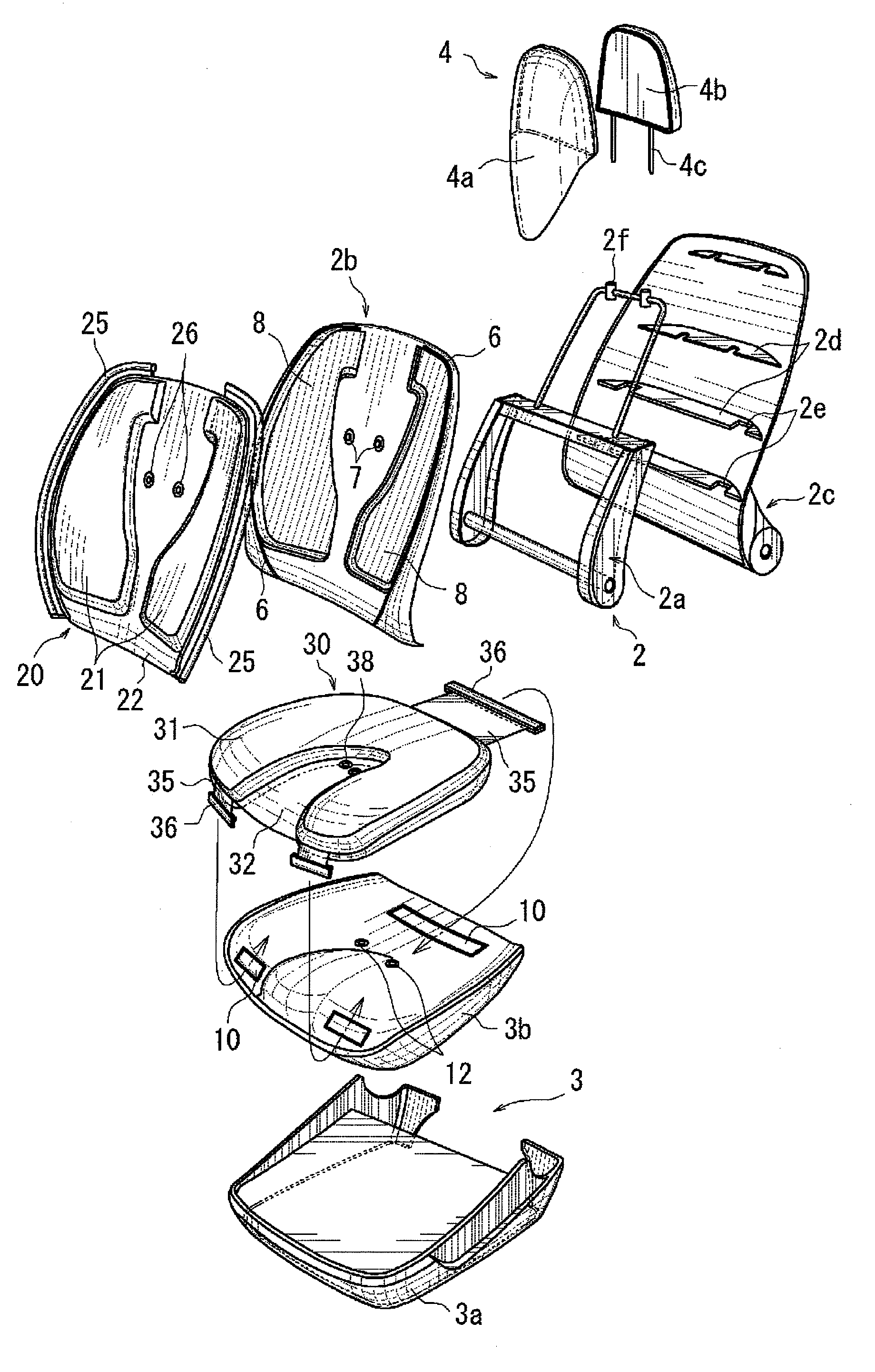
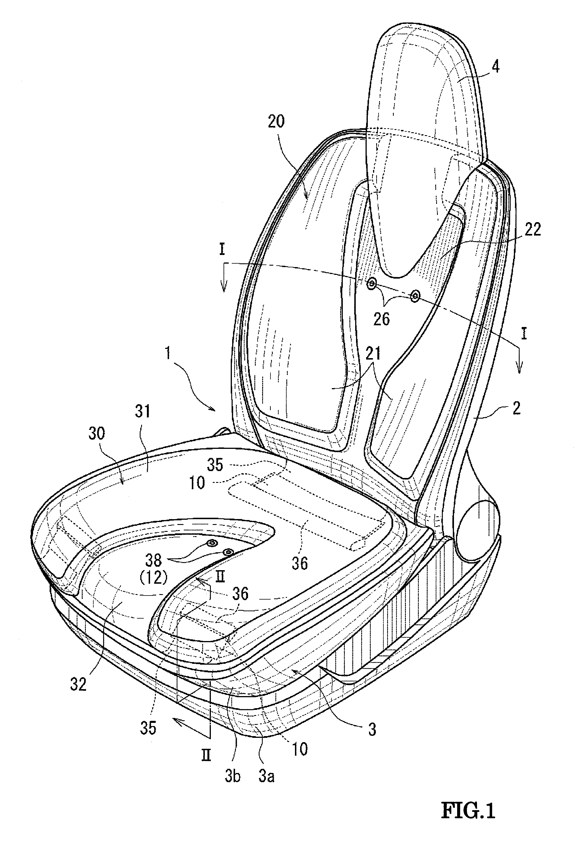
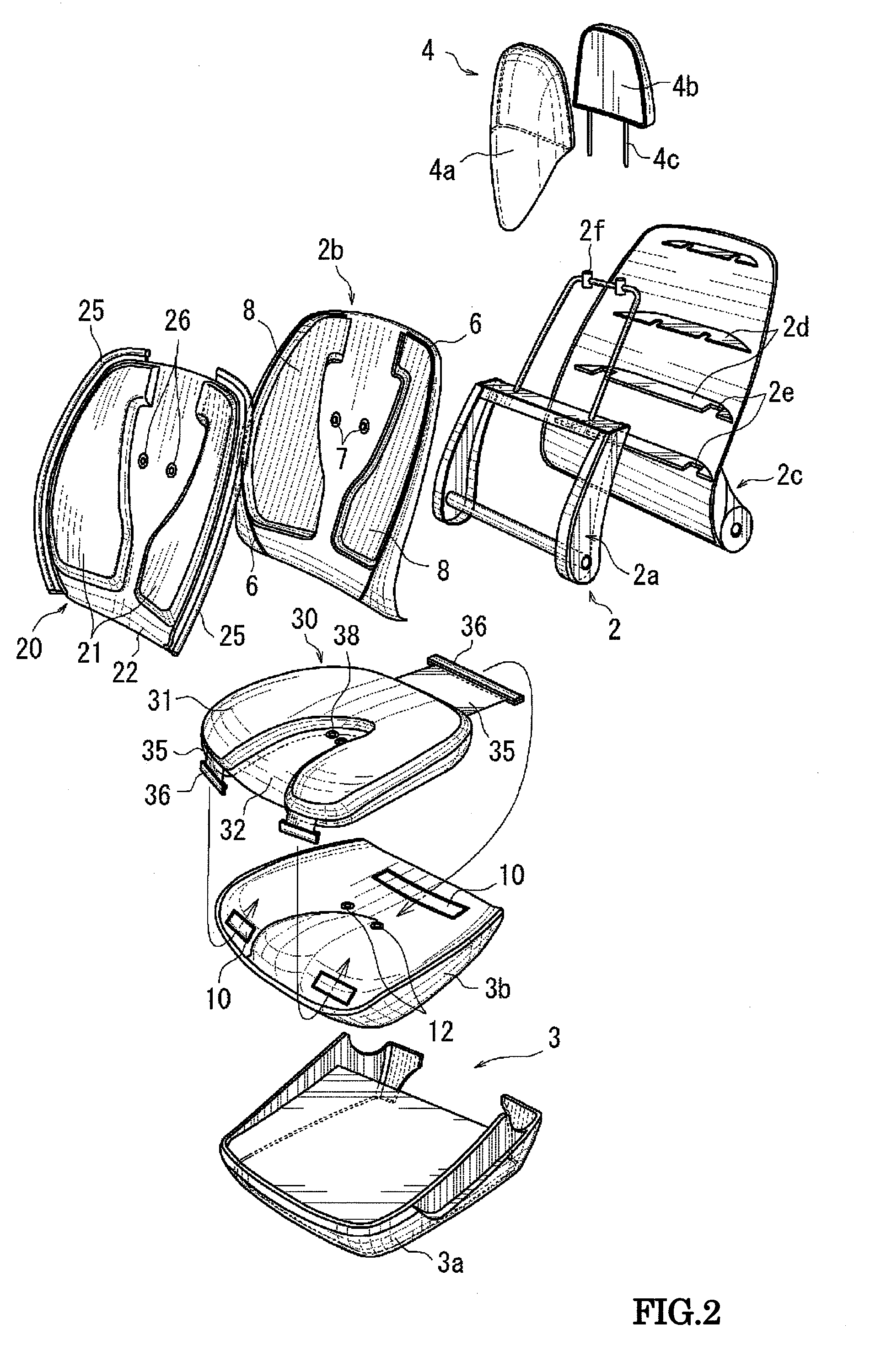
[0058]As shown by FIG. 1, a seat main body 1 includes a seat back 2 and a seat cushion 3 and a head rest 4. As shown by FIG. 2, the seat back 2 includes an inner frame 2a, and a front face panel 2b and a rear face panel 2c squeezing the inner frame 2a from a front and a rear direction. A front face of the front face panel 2b is attachably and detachably mounted with a back pad 20 as a seat pad for the seat back 2. The inner frame 2a, the front face panel 2b, and the rear face panel 2c are synthetic resin molded products. A front face of the rear face panel 2c is integrally formed with a plurality of steps of ribs 2d in an up and down direction. When the inner frame 2a is squeezed by the front face panel 2b and the rear face panel 2c, the inner frame 2a is contained in a plurality of recesses 2e notched to be formed at predetermined portions of the respective ribs 2d of the rear face panel 2c. Further, an illustration of a small member or mechanism of a reclining mechanism of the sea...

embodiment 2

[0083]Embodiment 2 is a modified example of Embodiment 1, and basic modes of the seat main body 1 and the back pad 20 and the cushion pad 30 are similar to those of Embodiment 1. As points different from Embodiment 1, as shown by FIG. 12 and FIG. 13, core members 29•39 for holding shapes are respectively included at inner portions of the laminated layers portions 21•31 of the back pad 20 and the cushion pad 30. Further, at the cushion pad 30, the single layer portion 32 is not present at the surface of the cushion pad 30, and also the snap button 38 as the attaching means is provided by way of the fabric belt 35. An explanation will be given centering on a difference from Embodiment 1.

[0084]First, an explanation will be given of the cushion pad 30 having a number of things different from Embodiment 1. Although according to the cushion pad 30 of Embodiment 2, a textile fabric having the plurality of laminated layers portion 31 substantially in a U-like shape by the same pattern simil...


PUM

PropertyMeasurementUnit
Thicknessaaaaaaaaaa
Coloraaaaaaaaaa
Flexibilityaaaaaaaaaa

Abstract

Seat pads of the present invention are sewn by hollow weave, and includes skins having single sheets of woven cloth integrally continuously having single layer portions and laminated layers portions in a shape of a hollow bag, and cushioning members enclosed at inner portions of the laminated layers portions and having a shape the same as that of the laminated layers portion and having an elasticity, the laminated layers portions are formed at portions of the single sheets of woven cloth intended to support the physical body of a seated person, the cushioning members are provided with predetermined thicknesses, the laminated layers portion are formed with recesses and projections of the same shape projected by a predetermined amount from head and tail faces of the single layer portions, and attachably and detachably mounted to a seating face of a seat, a recessed portion constituting a shape the same as that of the laminated layers portion is formed at a position of the seating face of the seat facing the laminated layers portions, and when mounted to the seat, the laminated layers portions are contained in the recessed portion of the seating face.

Description

TECHNICAL FIELD[0001]The present invention relates to a seat pad of an attachable and detachable type mounted to a seating face of a seat and a method of fabricating the same, as well as a seat mounted with the attachable and detachable type seat pad attachably and detachably to and from a seating face of the seat.BACKGROUND OF THE INVENTION[0002]As a seat pad of this kind, there is, for example, Patent Reference 1. A seat of Patent Reference 1 divides a seat pad into a plurality of pieces of unit pads and mounts the respective unit pads attachably and detachably to and from a seating face of a seat main body. Each of the unit pads is constituted by a cushioning member and a skin covered from thereabove, a lower end of the skin is provided with a plurality of pieces of engaging members in a shape of a hook, and the unit pad is mounted thereto by hanging to fix the respective engaging members to engaging holes bored at predetermined portions on a seat surface.[0003]Further, there is ...

Claims


Application Information

Patent Timeline
IPC IPC(8): A47C7/02B68G7/00
CPCA47C7/021A47C7/18A47C7/38A47C7/425Y10T29/481B60N2/643B60N2/646B60N2/7005B60N2/5891A47C7/0213
Inventor TARUMI, AKIRAYASUDA, HITOSHISHINOHARA, KAZUKIMI
Owner TOYOTA BOSHOKU KK
Why Eureka
Try Eureka