Output voltage compensation device

Inactive Publication Date: 2010-02-04
L&K PRECISION TECH CO LTD
View PDF7 Cites 2 Cited by
  • Summary
  • Abstract
  • Description
  • Claims
  • Application Information

AI Technical Summary

Benefits of technology

[0005]Accordingly, an object of the present invention is to provide an output voltage compensation device which e

Problems solved by technology

This solution, however, can not com

Method used


Image

  • Output voltage compensation device
  • Output voltage compensation device
  • Output voltage compensation device

Examples


Embodiment Construction

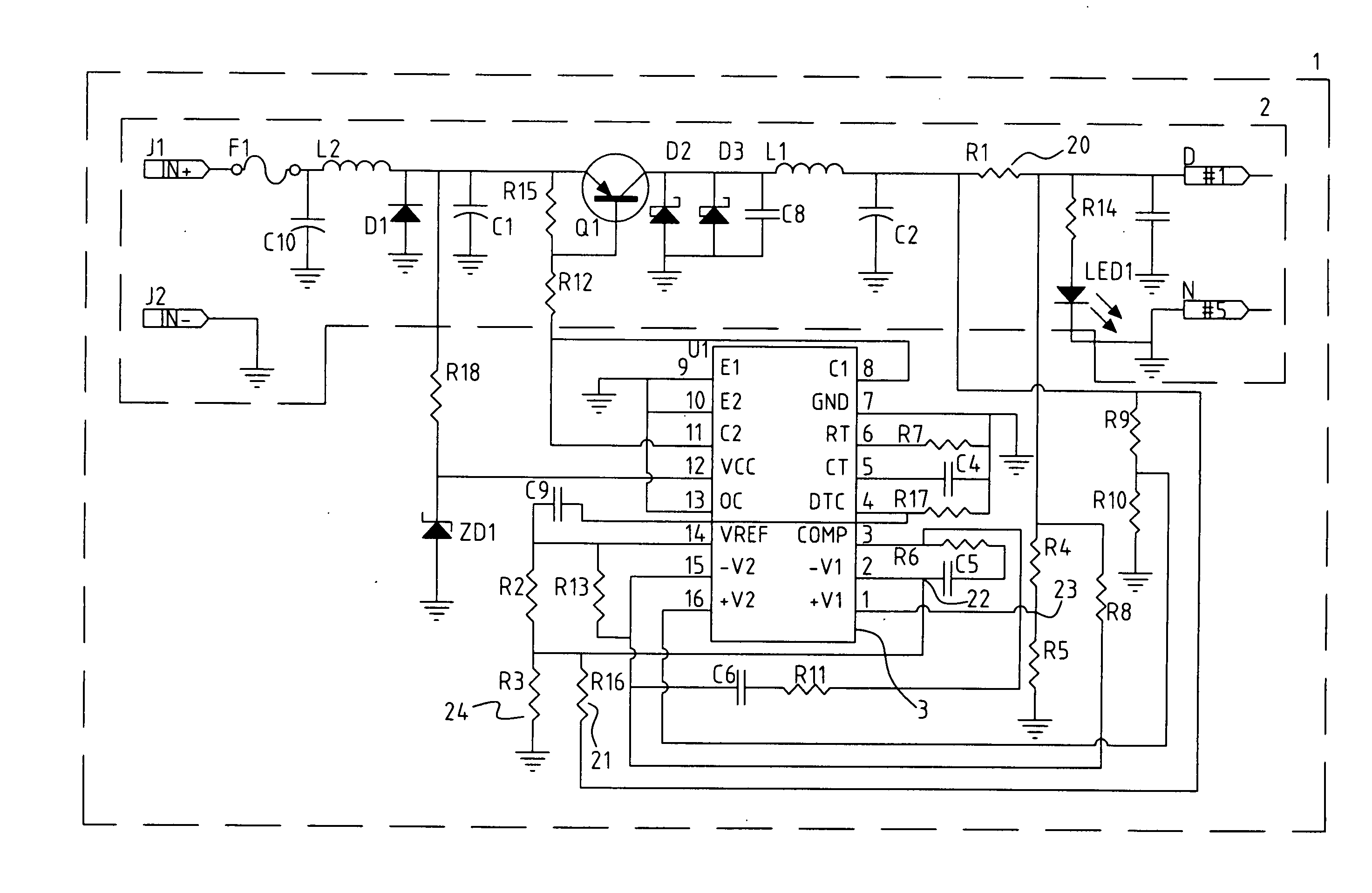
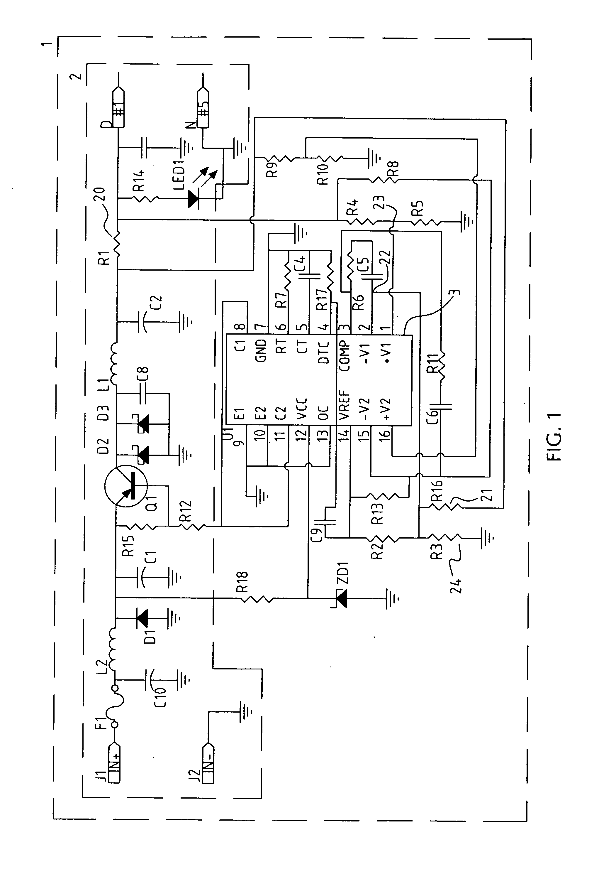
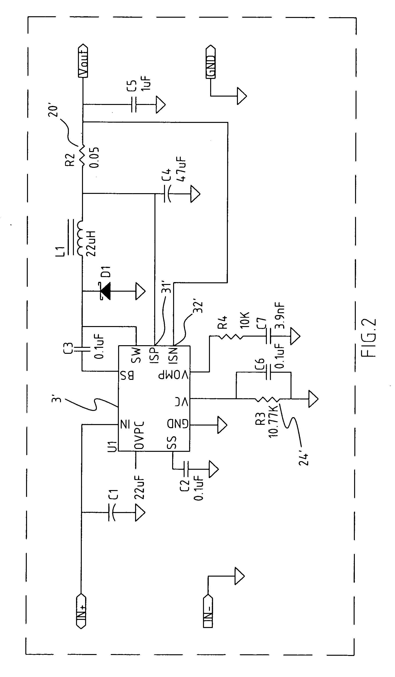
[0010]FIG. 1 shows an output voltage compensation device according to a first embodiment of the present invention. With reference to FIG. 1, the output voltage compensation device comprises a Buck converter 2, a current detection resistance 20, a sense resistance 21, a voltage-divide resistance 24, a voltage setting point 22, a voltage feedback point 23 and a Pulse Width Modulation (PWM) controller 3. The PWM controller 3 may be similar products available on market. The current detection resistance 20 is connected with an output end of the Buck converter 2. A front end of the current detection resistance 20 is connected by wire with the sense resistance 21. The sense resistance 21 detects variation of voltage rise between two ends of the sense resistance 21 due to rise of output current. The voltage rise passes the sense resistance 21 and is voltage divided by the voltage-divide voltage 24, and finally raises the set voltage at the voltage setting point 22 of the PWM controller 3. M...


PUM


Abstract

An output voltage compensation device has a Bark converter, a current detection resistance, a sense resistance, a voltage feedback circuit and a Pulse Width Modulation (PWM) controller. The current detection resistance is series connected with an output end of the Bark converter. Voltage at a front end of the current detection resistance is detected by the sense resistance, and compares with actual output voltage. Based on the compared result, the PWM controller adjusts work cycle of the Bark converter for voltage compensation.

Description

BACKGROUND OF THE INVENTION[0001]1. Field of the Invention[0002]The present invention relates to an output voltage compensation device, and particularly relates to an output voltage compensation device which compensates voltage consumed by wire resistance and connector resistance so that output voltage adjustment ratio coincides with practical design.[0003]2. Related Art[0004]Recently portable electronic products are booming. Correspondingly, vehicle charge products have tendency of raising output current specification to be adapted for the electronic products. Circuit voltage relatively rises, making voltage adjustment ratio be apt to exceed acceptable scopes of the electronic products. A conventional solution is to provide a V sense wire on output wire for detecting actual output voltage of the end of output wire and compensating output voltage. This solution, however, can not compensate output voltage effectively.SUMMARY OF THE INVENTION[0005]Accordingly, an object of the present...

Claims


Application Information

Patent Timeline
IPC IPC(8): G05F1/10
CPCH02M3/156
Inventor ZHIANG, JACK
Owner L&K PRECISION TECH CO LTD
Why Eureka
Try Eureka