Heat sink and assembly or module unit

Active Publication Date: 2013-10-15
ROGERS GERMANY
View PDF15 Cites 2 Cited by
  • Summary
  • Abstract
  • Description
  • Claims
  • Application Information

AI Technical Summary

Benefits of technology

[0013]The compensating layer which is provided on the at least one cooling surface of the cooling element and which is applied directly to the metal of the cooling element achieves or provides for effective compensation of the differing thermal expansion coefficients between the cooling element and the functional elements or components of an assembly or module connected with it by means of the solder

Problems solved by technology

Problematic, however, is the fact that the solder bond or solder layer between the respective cooling element and the part of the constructional or modular unit comprising the at least one electric component, due to the generally widely differing thermal expansion coefficients of the components connected with each other

Method used


Image

  • Heat sink and assembly or module unit
  • Heat sink and assembly or module unit
  • Heat sink and assembly or module unit

Examples


Embodiment Construction

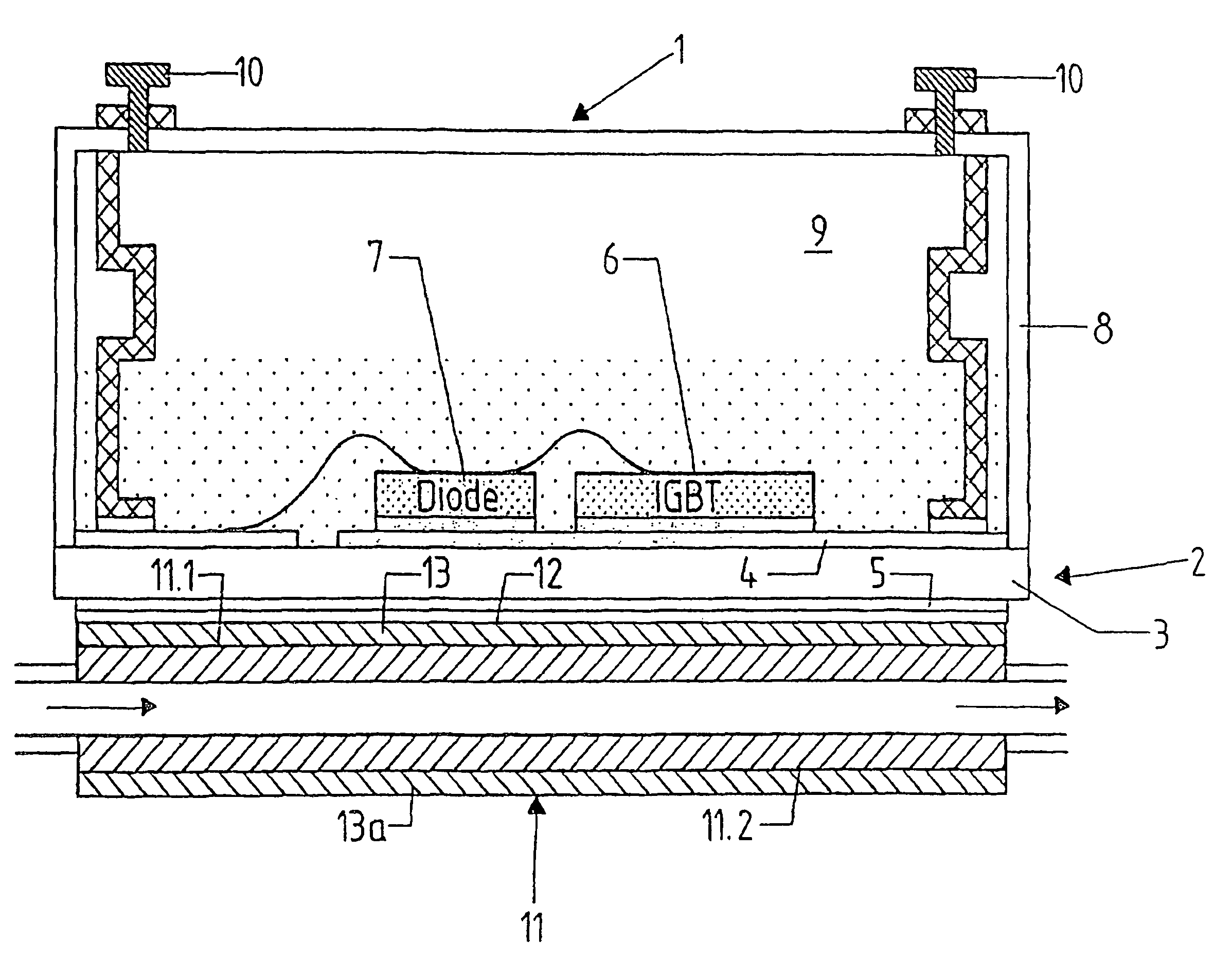
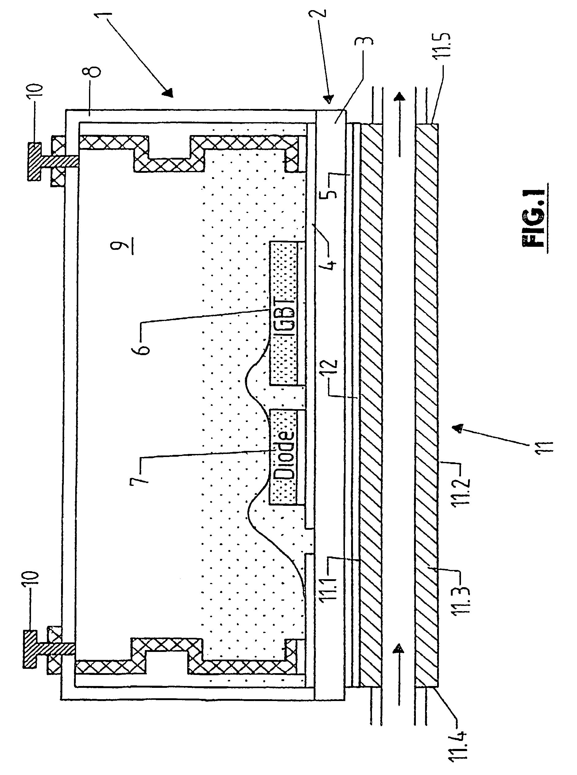
[0020]In FIG. 1, an electric or electronic power module 1, made up of a ceramic-metal substrate 2, namely of a DCB substrate made of a ceramic layer 3, is provided on both sides with a metallization 4 or 5. The metallizations 4 and 5 are formed respectively by copper foils, which are applied full-surface to the respective top surface side of the ceramic layer 3 by means of DCB technology. The ceramic layer 3 is for example made of an aluminum oxide (Al2O3) ceramic or an aluminum nitride (AlN) ceramic. The thickness of the ceramic layer 3 is for example between 0.2 and 2 mm.

[0021]The metallization 4 of the top side of the ceramic layer 3 is structured for forming conductors, contact surfaces, etc. Electronic components are attached to the metallization 4, namely for example a power component 6, e.g. in the form of an electronic switch element (IGBT) and further controlling components 7. The components 6 and 7 are housed in a closed housing 8, which is made of plastic, for example. Th...


PUM


Abstract

A heat sink for cooling parts, subassemblies, modules, or similar components, for cooling electrical or electronic components. The heat sink includes at least one cooling element which forms at least one cooling area for connecting the component that is to be cooled and which is made of a metallic material in the cooling area.

Description

BACKGROUND OF THE INVENTION[0001]The invention relates to a heat sink and to an assembly or module unit or arrangement.[0002]It is generally a standard and necessary practice to cool electrical or electronic components or assemblies, in particular power components or assemblies or modules to dissipate heat loss, namely by means of at least one heat sink (cooler) comprising at least one cooling element. For this purpose, the existing art uses in particular heat sinks with cooling elements in which at least one, preferably highly branched cooling channel structure is provided, through which a liquid and / or gaseous and / or vaporous heat-transporting or medium or cooling medium, for example water, can flow.[0003]For optimal cooling, it is advantageous in many cases to connect such components or assemblies by means of a solder bond to an outer cooling surface of the cooling element of the heat sink. The cooling element in this case, at least in the area of its outer cooling surface, is ma...

Claims


Application Information

Patent Timeline
IPC IPC(8): H01S3/04
CPCH01L23/3735H01S5/02476H05K7/20481H01L25/072H01L25/18H01L2224/48137H01L2224/48472H01L2224/73265H01L2924/0102H01L2924/01079H01L2924/13055H01S5/02272H01S5/02423H01S5/02469H01S5/4025H01L24/48H01L2924/01019H01L2924/01068H01L2924/01322H01L2224/48227H01L2924/00H01L2224/32225H01L2924/00012H01L2224/48091H01L2924/00014H01L24/73H01L2924/181H01L2224/48139H01S5/0237H01L2224/45099H01L2224/45015H01L2924/207
Inventor HAMMEL, ERNSTSCHULZ-HARDER, JURGEN
Owner ROGERS GERMANY
Why Eureka
Try Eureka