Image display device

Active Publication Date: 2010-02-04
BROTHER KOGYO KK
View PDF14 Cites 36 Cited by
  • Summary
  • Abstract
  • Description
  • Claims
  • Application Information

AI Technical Summary

Benefits of technology

[0007]It is extremely advantageous for the eyeglasses-mountable-type image display device if the display device could be easily mounted on the eyeglasses. On the other hand, the eyeglasses-mountable-type image display device has following drawbacks. That is, it is difficult to mount the image display device at an optimum position at a first attempt when a user mounts the image

Problems solved by technology

That is, it is difficult to mount the image display device at an optimum position at a first attempt when a user mounts the image display device on the eyeglasses and the posture of the image display device mounted on the eyeglasses is liable to become easily unstable.
Accordingly, in adjusting a position of the display mounted on the eyeglasses, the mere release of the clip cannot mov

Method used


Image

  • Image display device
  • Image display device
  • Image display device

Examples


Example

[0023]The present invention is explained hereinafter in detail in conjunction with attached drawings.

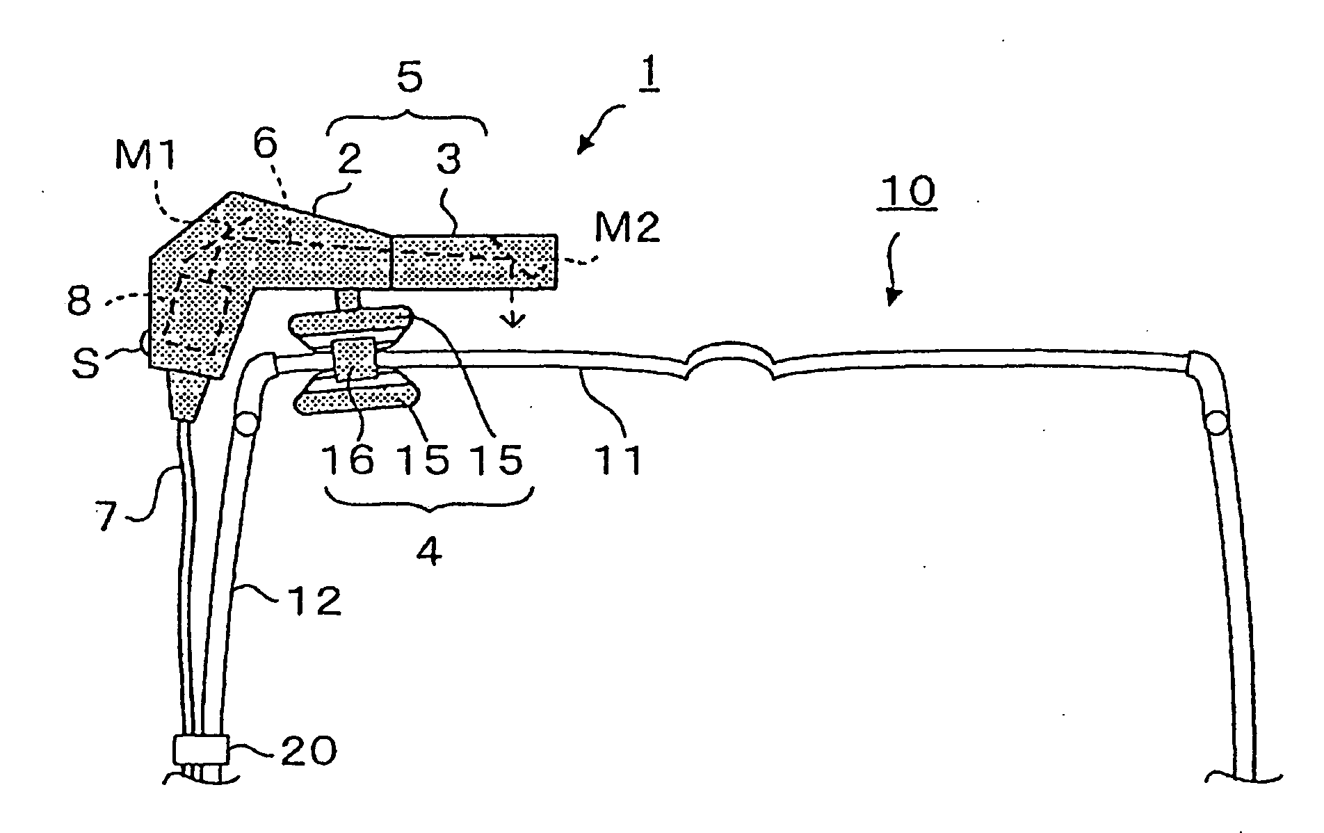
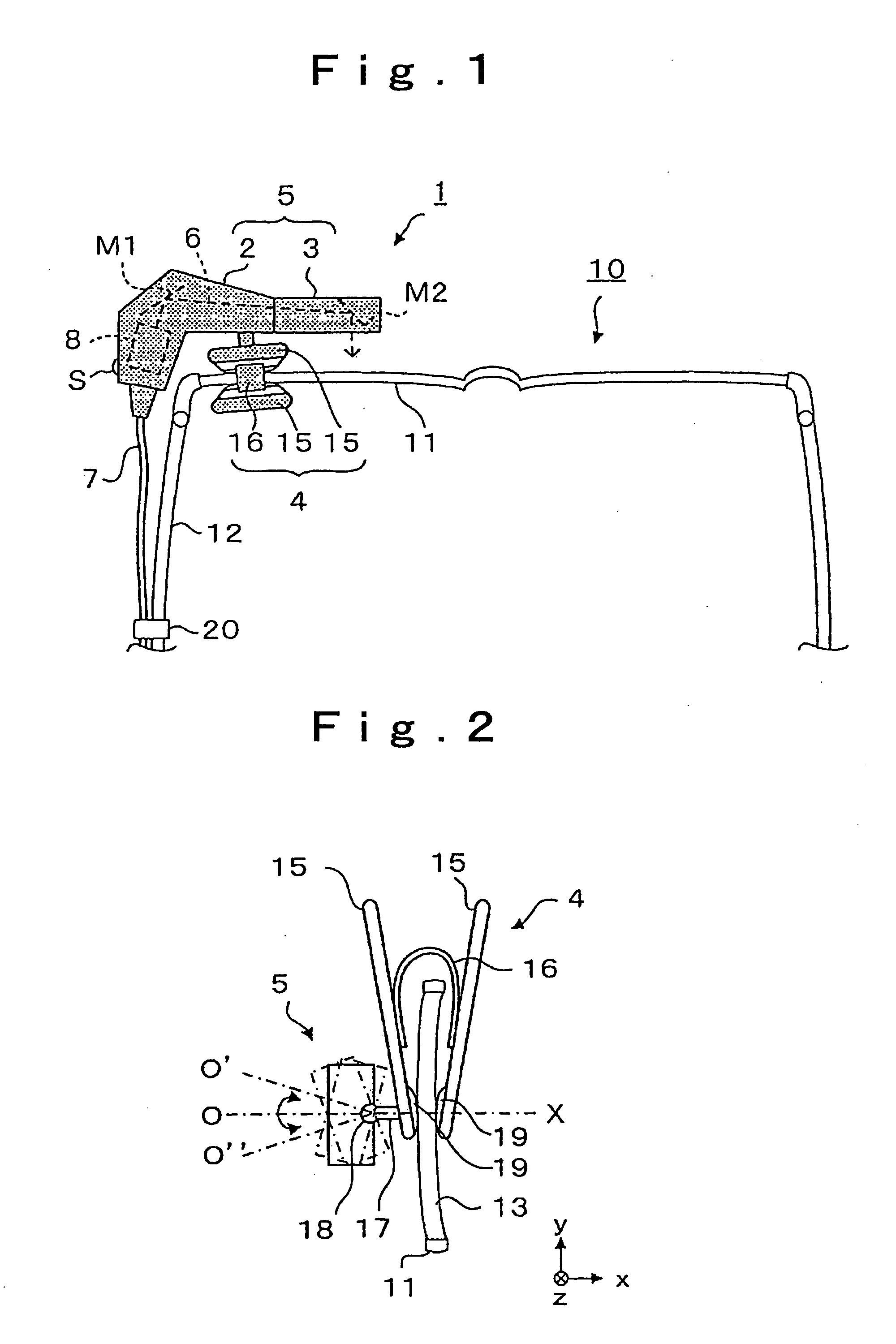
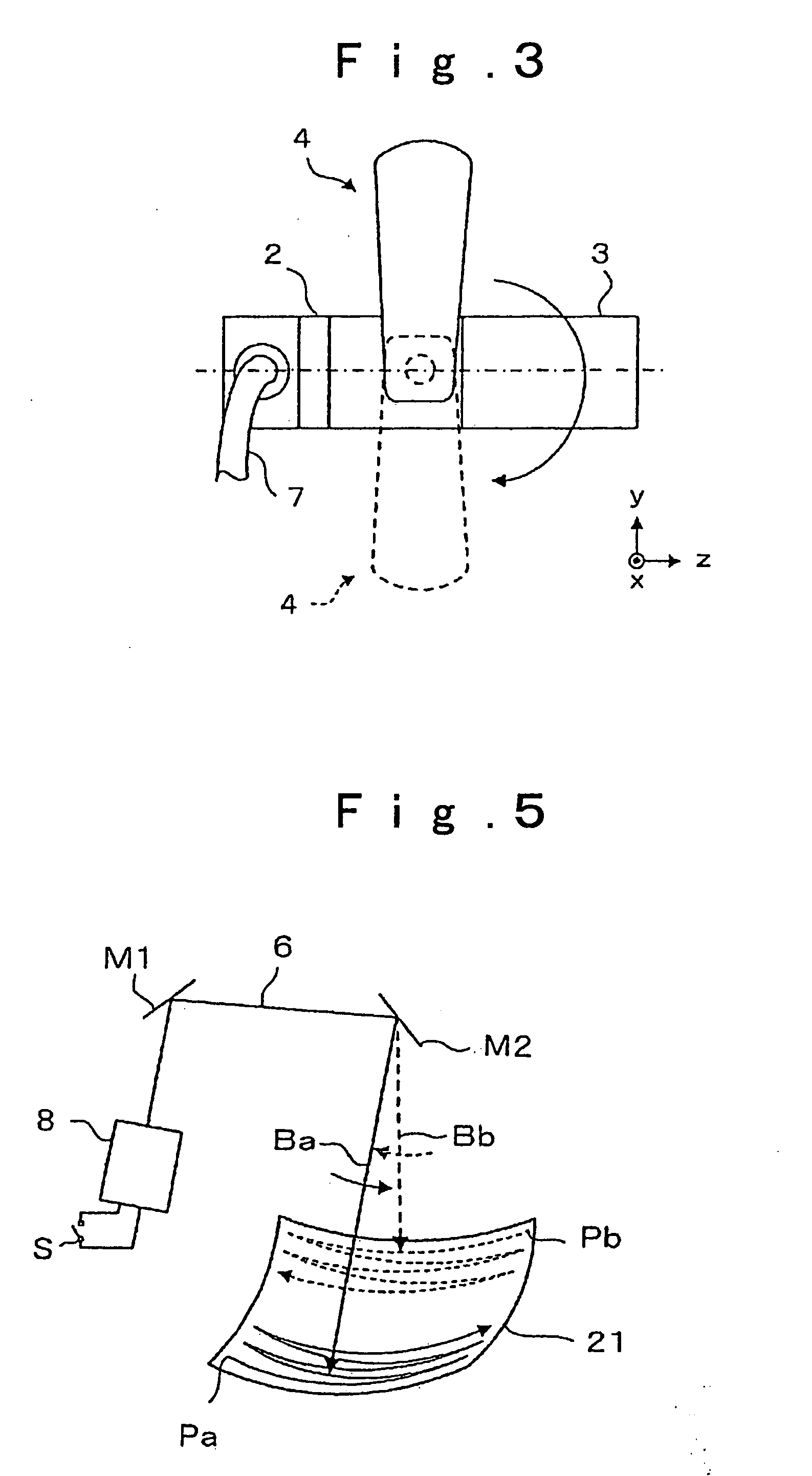
[0024]As shown in FIG. 1, an image display device 1 (being explained as a monocular image display device in this embodiment) is constituted of an image projection part 5 which generates an image and projects the image on a retina of a user, and a clip 4 mounted on the image projection part 5. The image projection part 5 is held on and fixed to the eyeglasses 10 by clamping a part of a lens portion of the eyeglasses 10 with the clip 4 from a front surface side and a back surface side of the eyeglasses 10. The image projection part 5 is constituted of an image forming part 2 which forms an image, and a prism 3 which introduces the formed image therein and projects the image on a retina of a user not shown in the drawing. The image forming part 2 includes an image scanning part 8 which converts video signals received via a lead line 7 into scanning beams 6, reflection surfaces M1 and M2...


PUM


Abstract

The eyeglass-mountable image display device is an image display device which includes an image projection part and a clip which is mounted on the image projection part. The image projection part is held on eyeglasses by the clip which clamps a part of a lens portion of the eyeglasses from both surface sides of the lens portion.

Description

CROSS-REFERENCE TO RELATED APPLICATIONS[0001]The present application is a Continuation-in-Part of International Application No. PCT / JP2008 / 055031 filed on Mar. 19, 2008, which claims the benefit of Japanese Patent Application No. 2007-080037 filed on Mar. 26, 2007.BACKGROUND[0002]1. Field[0003]The present invention relates to an image display device which allows a user to observe an image or the like with the image display device mounted on eyeglasses.[0004]2. Description of the Related Art[0005]If a miniaturized display can be simply mounted on eyeglasses or the like of a user, the user could enjoy images at any place and hence, such a miniaturized display becomes convenient. To satisfy such a demand, there has been proposed a miniaturized image display device which directly projects an image on a retina of a user from a position near an eyeball of the user. For example, as shown in FIG. 11, there has been proposed an eyeglasses-mountable-type image forming apparatus. The image for...

Claims


Application Information

Patent Timeline
IPC IPC(8): G03B21/14G02C11/00
CPCG02B27/0176G02B2027/0156H04N5/7491G02C9/04H04N5/74G02B2027/0178
Inventor TANAKA, MITSUGI
Owner BROTHER KOGYO KK
Why Eureka
Try Eureka