Simplified deployment modeling

Inactive Publication Date: 2010-02-04
IBM CORP
View PDF72 Cites 122 Cited by
  • Summary
  • Abstract
  • Description
  • Claims
  • Application Information

AI Technical Summary

Benefits of technology

[0026]FIG. 18 is a block diagram of an exemplary computer system including a computer usable medium having computer usable program code embodied therewith, where the exemplary

Problems solved by technology

However, the development environment from which a new application is developed is often different from an operations environment, e.g., a data center, which deploys the developed application.
In this regard, architects within the operations environment are typically burdened with the responsibility of carrying the developed application into operations.
However, the architects within the operations environment often do not have first-hand knowledge of the developed artifacts, e.g., the details, requirements specifications, configuration directives, etc., associated with the application to be deployed.
This can result in difficulty for successful deployment of the application within the operations environment, especially when that entity is forced to deal with solving configuration problems that arise from incompatibilities in the requirements of the developed appl

Method used


Image

  • Simplified deployment modeling
  • Simplified deployment modeling
  • Simplified deployment modeling

Examples


Embodiment Construction

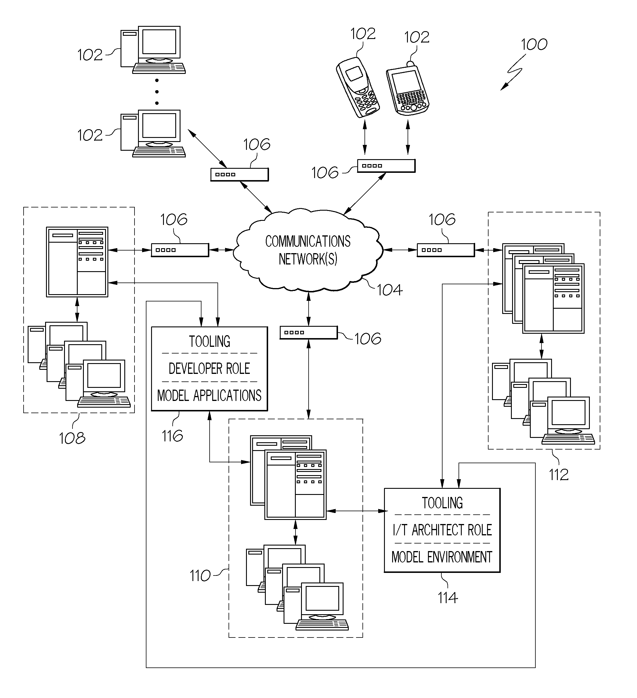
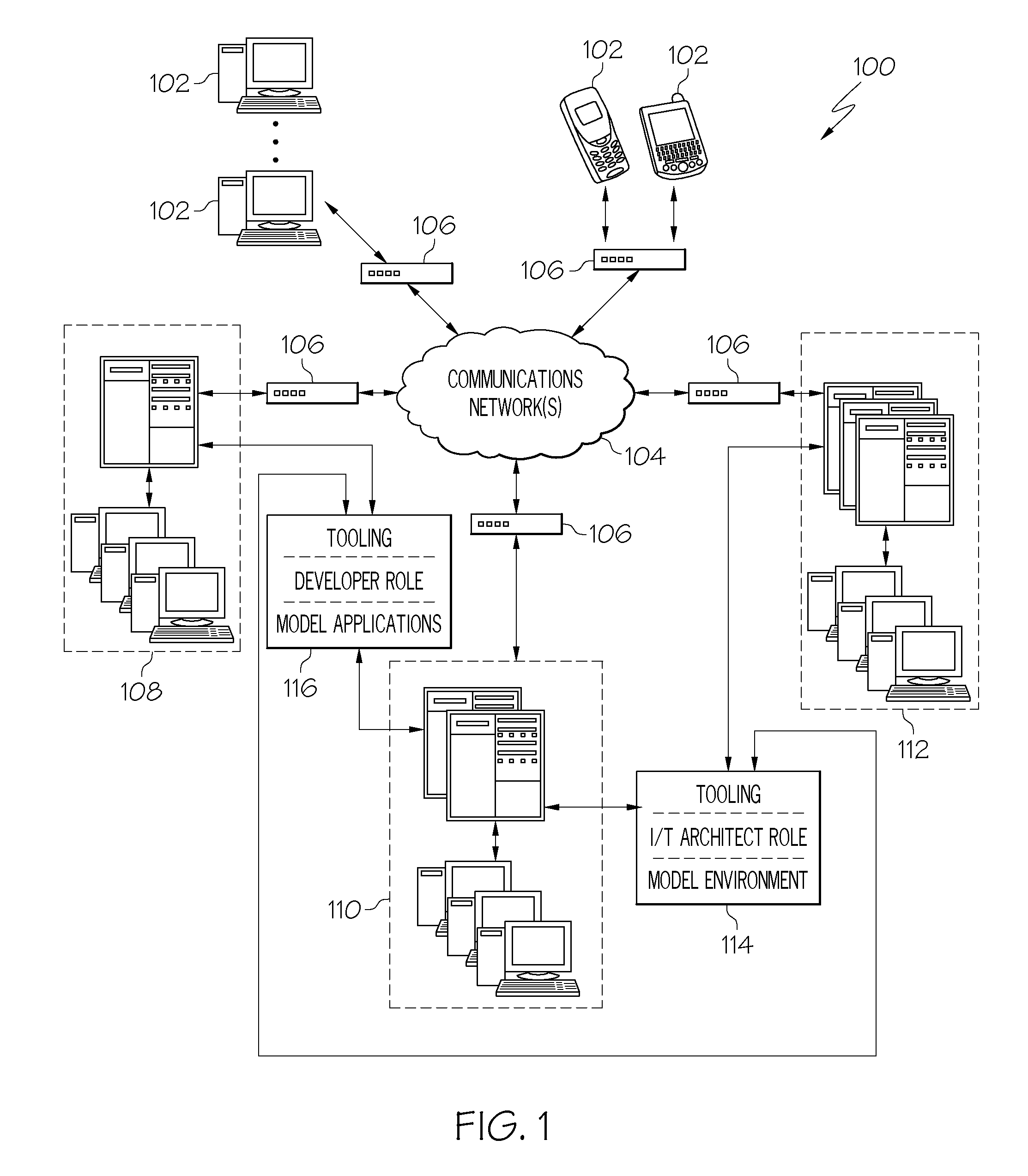
[0027]According to various aspects of the present invention, systems, methods and computer program products are provided for creating and utilizing a common tooling platform that allows a plurality of users, each implementing a different role, to work together by capturing the knowledge of each role and using the captured knowledge to communicate with the next role. In this regard, a deployment modeling platform is utilized to build extensible domain specific models that represent information technology (IT) knowledge at different levels of abstraction.

[0028]For example, the deployment modeling platform may facilitate the utilization of a formal construct that represents a real-world enterprise architecture. As such, the deployment modeling platform may be utilized to build models that capture the characteristics of the business and physical concerns of a distributed computing environment in an extensible manner that is actionable by ad-hoc processors. That is, the deployment modeli...


PUM


Abstract

A deployment modeling platform enables a user to model application characteristics of target software and to associate application modeling parameters to the modeled application characteristics. A user may also model environment characteristics of a target deployment environment and to associate environment modeling parameters to the modeled deployment environment characteristics. Still further, a user may create a deployment model that associates and maps selected parameters of the modeled application characteristics of the target software to associated parameters of the modeled environment characteristics of the deployment environment, and to verify that each parameter that relates to a requirement is mapped to and is fulfilled by an associated parameter that relates to a corresponding capability to determine whether validation problems exist in order to deploy the target software in the associated deployment environment.

Description

BACKGROUND OF THE INVENTION[0001]The present invention relates to systems, methods and computer program products that capture the characteristics of a business and physical concerns of a distributed computing environment in an extensible manner that is actionable by ad-hoc processors.[0002]In a typical application development environment, a software architect creates software applications, e.g., using conventional development tools. However, the development environment from which a new application is developed is often different from an operations environment, e.g., a data center, which deploys the developed application. In this regard, architects within the operations environment are typically burdened with the responsibility of carrying the developed application into operations. However, the architects within the operations environment often do not have first-hand knowledge of the developed artifacts, e.g., the details, requirements specifications, configuration directives, etc., ...

Claims


Application Information

Patent Timeline
IPC IPC(8): G06F9/44
CPCG06F8/61
Inventor ARNOLD, WILLIAM C.BERG, DANIEL C.BLANCETT, BRAD L.EILAM, TAMARELDER, MICHAEL D.HOLLIDAY, CHADKALANTAR, MICHAEL H.KONSTANTINOU, ALEXANDER V.POUYER, TIMOTHY A.MAKIN, NARINDERSLUIMAN, HARMSNIBLE, EDWARD C.SWANKE, JOHN E.TOTOK, ALEXANDER A.TROSSMAN, ANDREW N.
Owner IBM CORP
Why Eureka
Try Eureka