Fuel cell and gas separator for fuel cell
a fuel cell and separator technology, applied in the field of fuel cell and gas separator for the fuel cell, can solve the problems of difficulty in solving the non-uniform flow rate distribution of fluids
- Summary
- Abstract
- Description
- Claims
- Application Information
AI Technical Summary
Benefits of technology
Problems solved by technology
Method used
Image
Examples
second embodiment
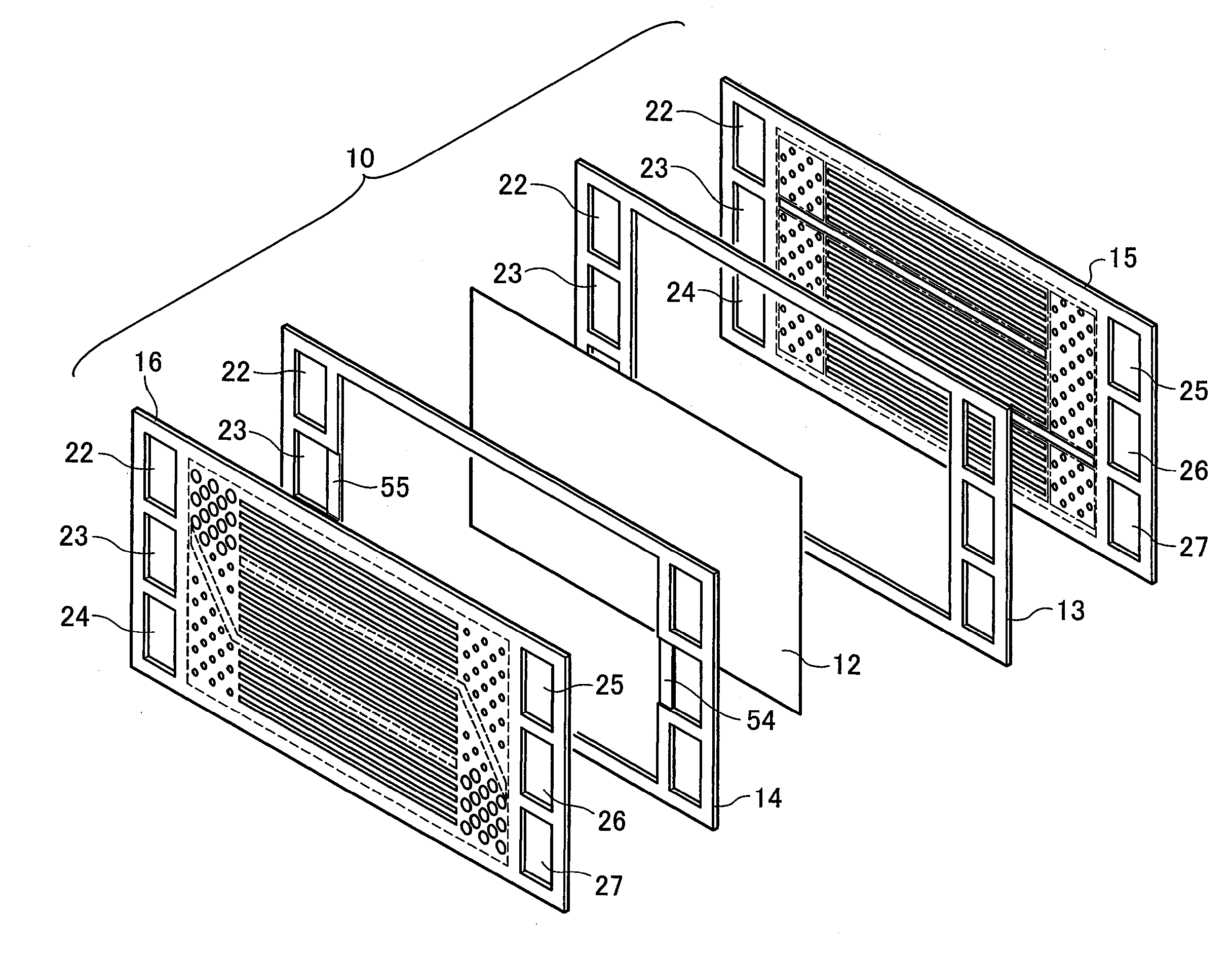
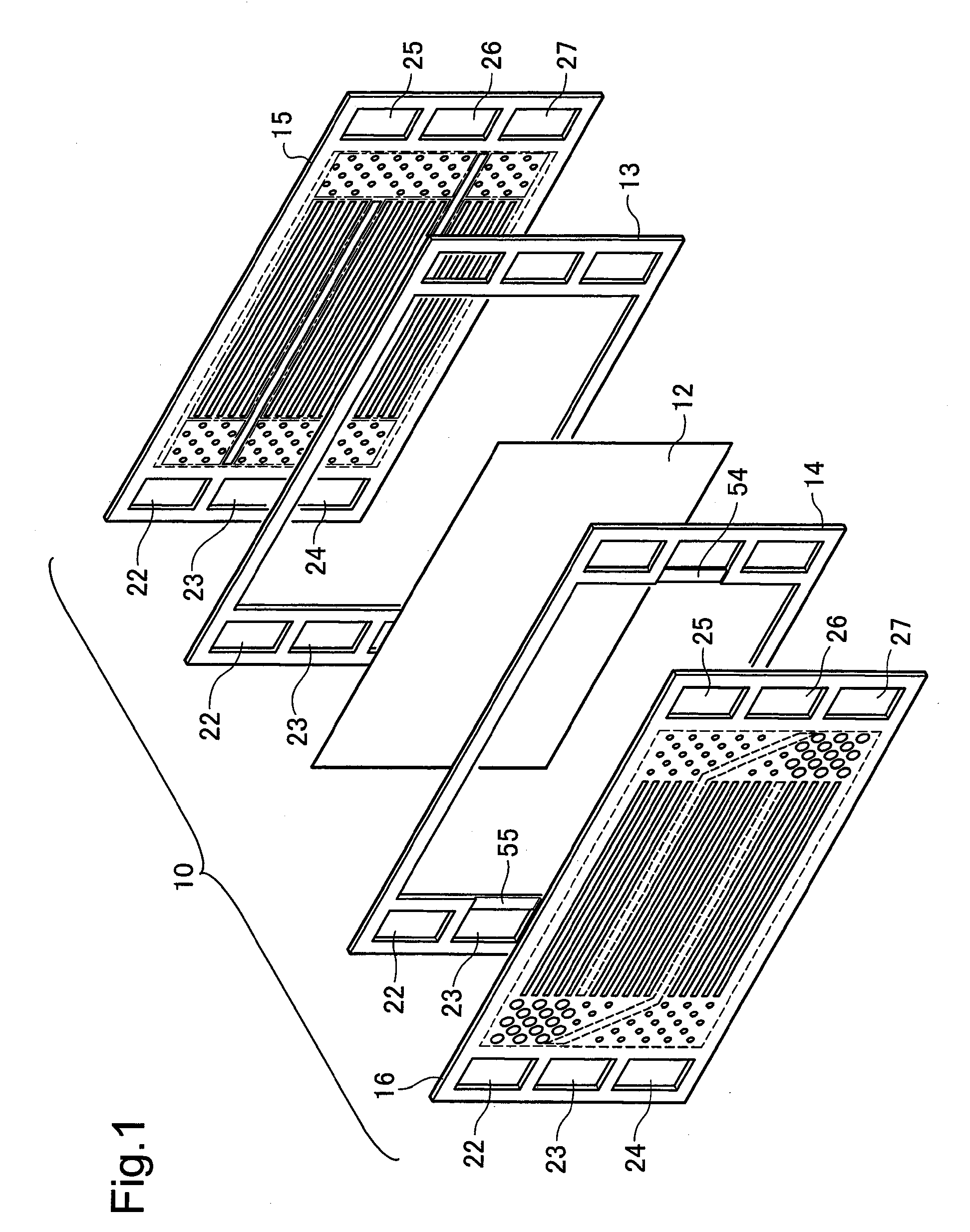
[0069]In the structure of the first embodiment, the refrigerant supply manifold and the refrigerant discharge manifold are arranged diagonally outside the substantially rectangular power generation area on the side of the separator. This arrangement is, however, neither essential nor restrictive. A fuel cell of another structure with a different layout of manifolds is discussed below as a second embodiment of the invention. The fuel cell of the second embodiment has the similar structure to that of the fuel cell of the first embodiment, except that the separators 15 and 16 are replaced with separators 115 and 116 and that recesses 54 and 55 (not shown) are provided in the vicinities of the holes 24 and 25 on the resin frame 14. The like elements are expressed by the like reference numbers and are not specifically explained here.
[0070]FIG. 7 is plan views showing the structure of the separator 115 included in the fuel cell of the second embodiment. FIG. 8 is plan views showing the st...
third embodiment
[0075]In the structure of the first embodiment, the projections 46 or 66 are formed to have the cross sections of the varying diameter in the flow distribution areas 35. Another structure may be adopted to vary the refrigerant flow resistance in the vertical direction by location. A fuel cell of another structure adopted to vary the refrigerant flow resistance in the vertical direction by location in the flow distribution areas 35 is discussed below as a third embodiment of the invention. The fuel cell of the third embodiment has the similar structure to that of the fuel cell of the first embodiment, except that the separators 15 and 16 are replaced with separators 215 and 216. The like elements are expressed by the like reference numbers and are not specifically explained here.
[0076]FIG. 9 is plan views showing the structure of the separator 215 included in the fuel cell of the third embodiment. FIG. 10 is plan views showing the structure of the separator 216 included in the fuel c...
modified example 1
[0084]In the structures of the first through the third embodiments discussed above, the two different sizes or different shapes of the projections 46 or 66 are used to vary the flow path resistance by location in the flow distribution areas 35. In one modified structure, projections of three or a greater number of different sizes or different shapes may be formed in the flow distribution area 35 to control the flow path resistance. For example, the size of the projections 46 or 66 may be gradually expanded toward the high refrigerant flow rate areas. In the structure of varying the size or the shape of the projections 46 or 66 in part of each flow distribution area 35 as in the structures of the first through the third embodiments, the high refrigerant flow rate area may be set to be wider in area or to be narrower in area than each of the parted regions 32a through 32c. On the refrigerant flow path area, the refrigerant flow generally runs straight in parallel to the horizontal dir...
PUM
 Abstract
Description
Claims
Application Information
 - R&D
- Intellectual Property
- Life Sciences
- Materials
- Tech Scout
- Unparalleled Data Quality
- Higher Quality Content
- 60% Fewer Hallucinations
Browse by: Latest US Patents, China's latest patents, Technical Efficacy Thesaurus, Application Domain, Technology Topic, Popular Technical Reports.
© 2025 PatSnap. All rights reserved.Legal|Privacy policy|Modern Slavery Act Transparency Statement|Sitemap|About US| Contact US: help@patsnap.com


