Electrical contact for socket connector

a technology of electrical contact and socket connector, which is applied in the direction of multiple conductor connector, coupling device connection, coupling device details, etc., can solve problems such as damage to electrical contact, and achieve the effect of more rigidity

Inactive Publication Date: 2010-02-11
HON HAI PRECISION IND CO LTD
View PDF8 Cites 5 Cited by
  • Summary
  • Abstract
  • Description
  • Claims
  • Application Information

AI Technical Summary

Benefits of technology

[0006]Accordingly, an object of the present invention is to provide an electrical contact having much more rigidity while keeping in small dimension.

Problems solved by technology

With a smaller dimension, the moveable part and the immoveable part are so thin that they have no enough rigidity, which easily causes damage to the electrical contact.

Method used


Image

  • Electrical contact for socket connector
  • Electrical contact for socket connector
  • Electrical contact for socket connector

Examples


Embodiment Construction

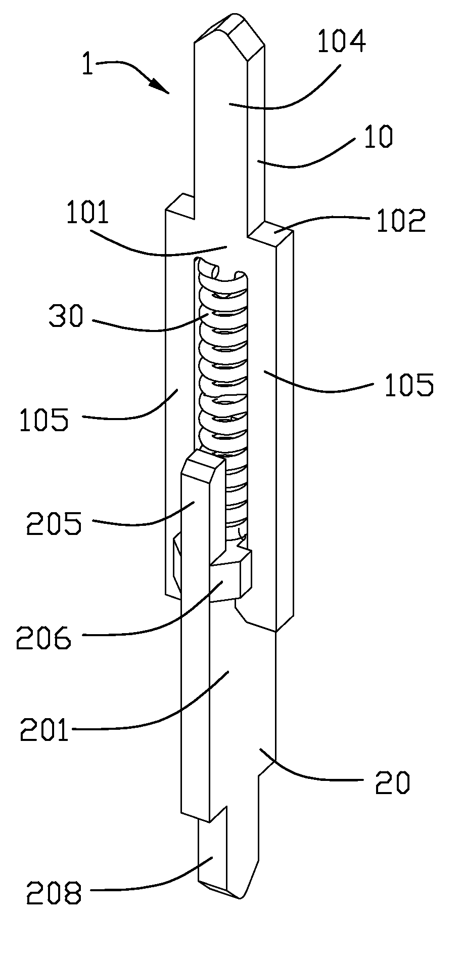
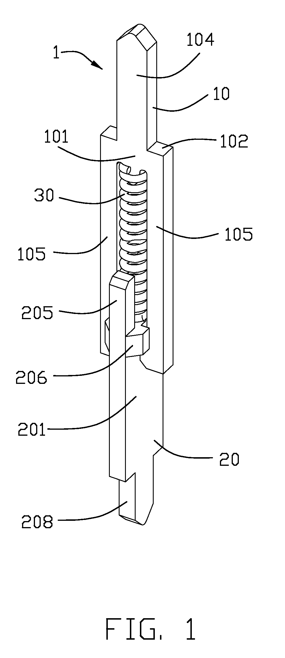
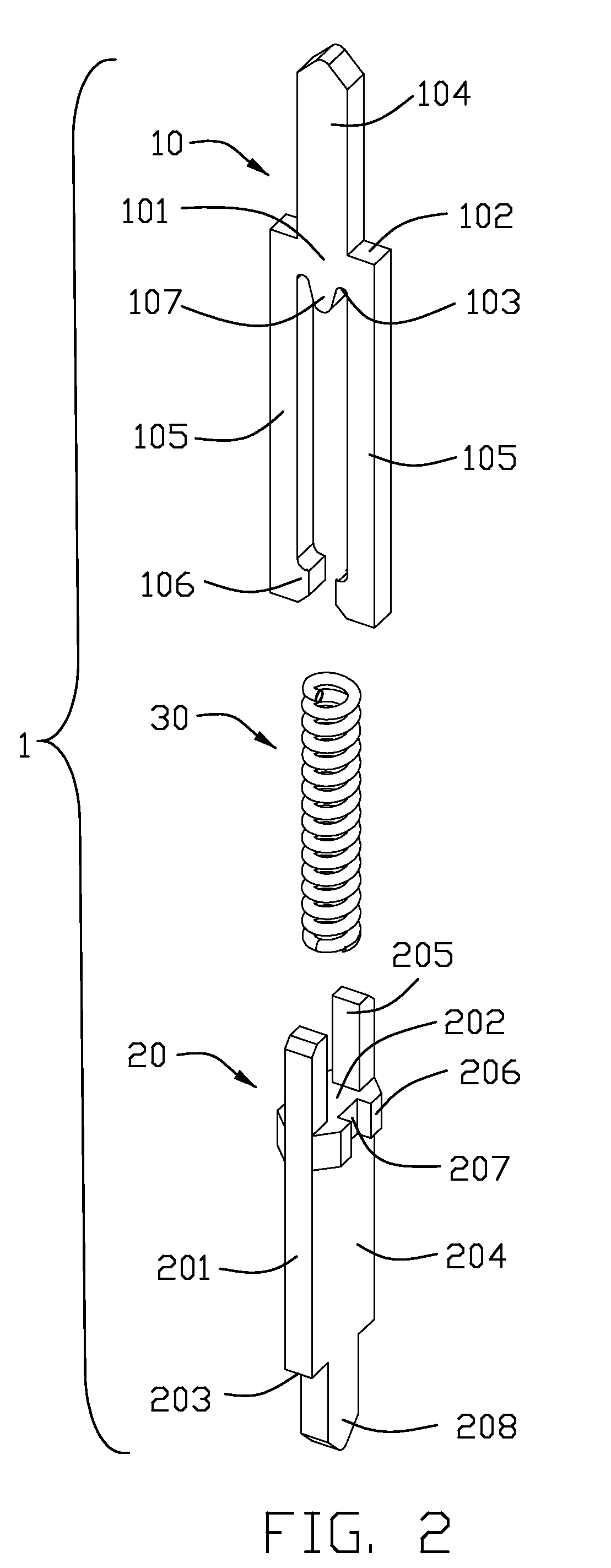
[0013]Referring to FIGS. 1-4, an electrical connector 100 of the present invention, used for connecting a central processing unit (CPU, not shown) with a printed circuit board (PCB, not shown), is described as following: the electrical connector 100 comprises an insulative housing 2 with a plurality of passageways 21 therein and a plurality of contacts 1 received in corresponding passageways 21. The contact 1 comprises a moveable part 10, an immoveable part 20 and a biasing device 30. The biasing device 30 is fitted over by the moveable and immoveable parts 10, 20 and provides resilient force therebetween.

[0014]Referring to FIG. 2, the moveable part 10 comprises a base portion 101. The base portion 101 defines an outer face 102 and an inner face 103 located at an opposite side of the outer face 102. The moveable part 10 further comprises a contact beam 104 extending upwardly from the outer face 102 for electrical connection with the CPU and a pair of guiding beams 105 extending down...


PUM


Abstract

An electrical connector (100) includes an insulative housing (2) defining a plurality of passageways (21) and a plurality of contacts (1) received in corresponding passageways. Each contact includes a moveable part (10) forming a pair of guiding beams (105), an immoveable part (20) coupled with the moveable part and a biasing device (30) constantly urging the moveable part away from immoveable part. The immoveable part includes a pair of posts (205) and defines a pair of guiding slots (207). The guiding beams are received in the guiding slots and are capable of moving with regard to the immovable part along opposite surfaces of the immoveable part. The guiding beams and the posts are decussated to surround the biasing device for preventing the biasing device from disengaging therefrom.

Description

BACKGROUND OF THE INVENTION[0001]1. Field of the Invention[0002]The present invention relates generally to an electrical socket connector, and more particularly to an electrical socket connector having electrical contacts which electrically connects a plurality of pins of an integrated circuit (IC) provided in a test socket to corresponding pads of a printed circuit board (PCB).[0003]2. Description of Related Arts[0004]U.S. Pat. No. 7,025,602 issued to Hwang on Apr. 11, 2006, discloses an electrical contact for connecting a central processing unit (CPU) with a printed circuit board (PCB). The electrical contact comprises a moveable part, a immoveable part and a spring portion. The spring portion is fitted over a predetermined area between the moveable and immoveable parts and provides resilient force therebetween. Whether the moveable part contacts with the immoveable part or not depends on the resilient force of the spring portion. In order to meet the minimization of the electrica...

Claims


Application Information

Patent Timeline
Patent Type & Authority Applications(United States)
IPC IPC(8): H01R24/00H01R4/48
CPCH01R13/2421
Inventor HSIAO, SHIH-WEIHSIEH, WEN-YI
Owner HON HAI PRECISION IND CO LTD
Why Eureka
Try Eureka