Magnetic cosmetics applicator
a cosmetics and applicator technology, applied in the field of magnetic cosmetics applicators, can solve the problems of inability to meet the needs of consumers, high risk of breakage of such a design, and the inability to have a certain size in the bristle carrier, so as to achieve the effect of improving haptic application behavior and maintaining flexibility
- Summary
- Abstract
- Description
- Claims
- Application Information
AI Technical Summary
Benefits of technology
Problems solved by technology
Method used
Image
Examples
embodiment examples
Example 1
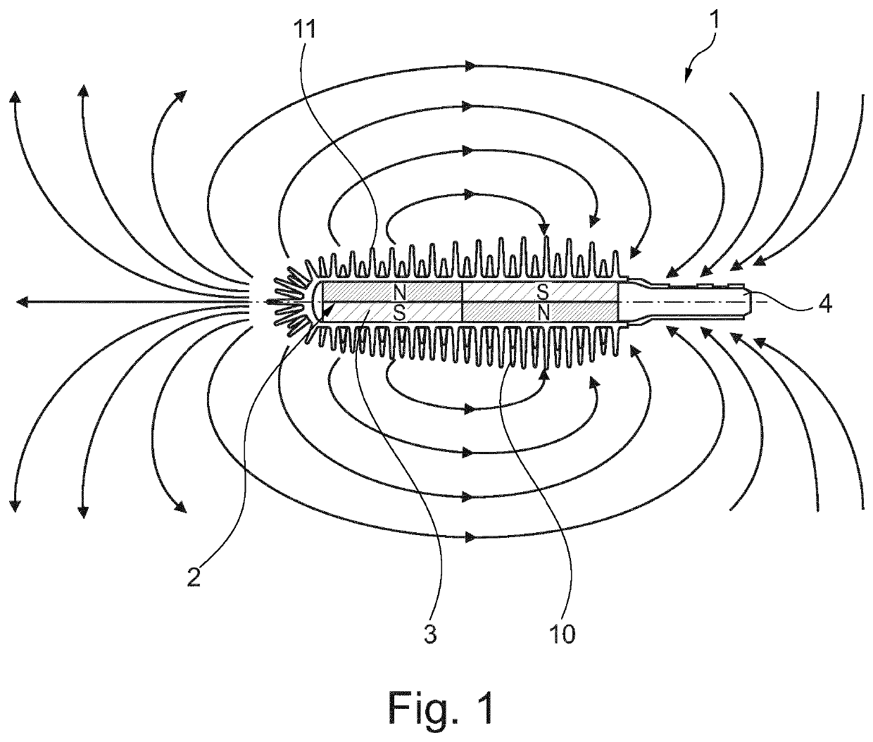
[0038]FIG. 1 provides a good overview of the invention, showing a general example of the applicator 1 according to the invention.
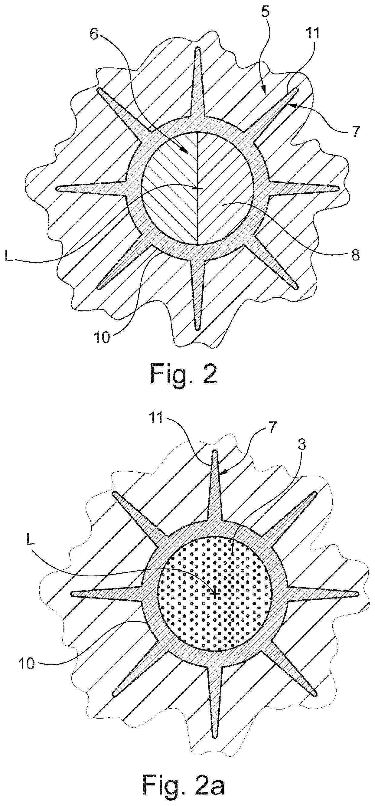
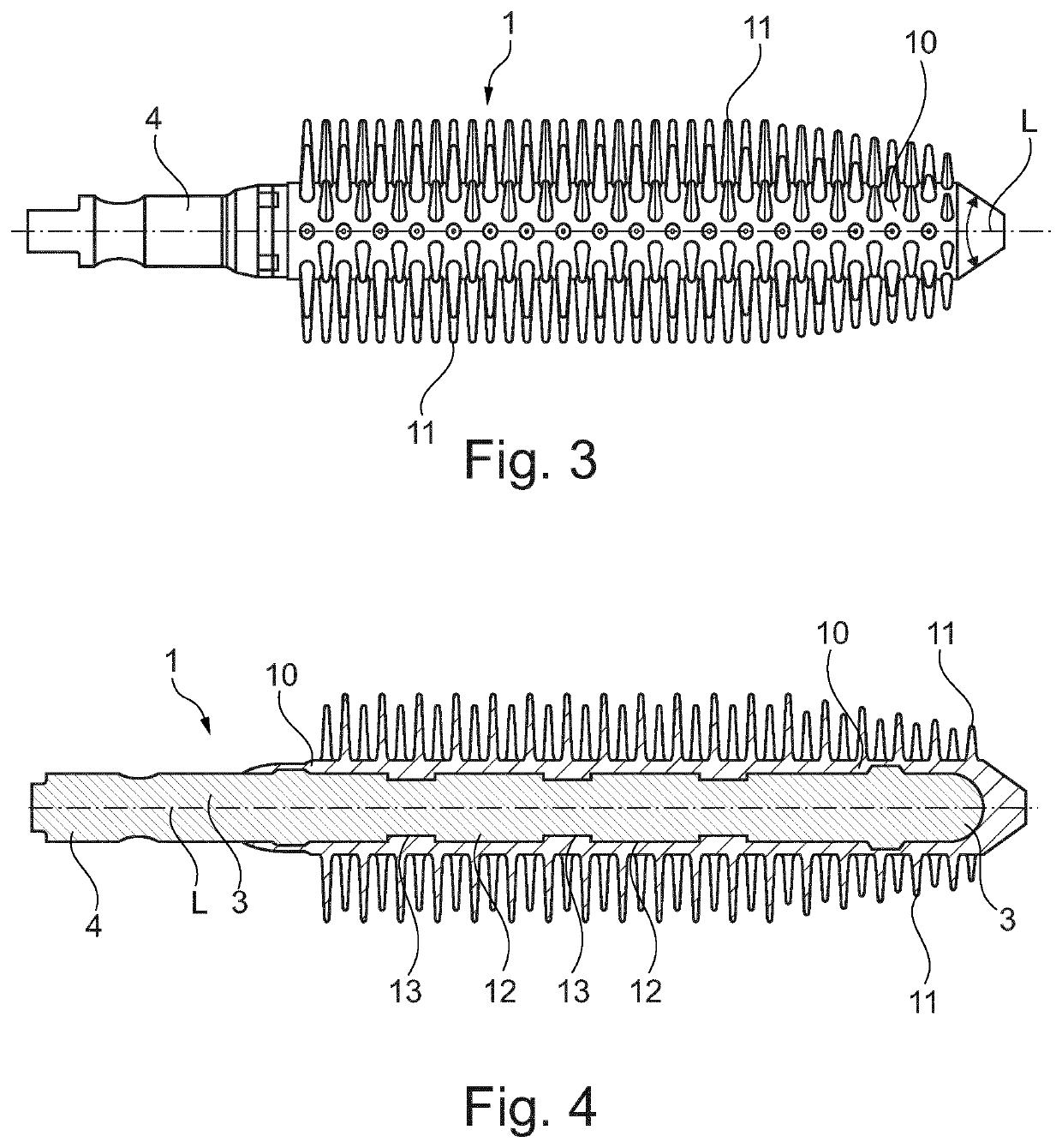
[0039]As is evident, the applicator 1 comprises a bristle carrier 2. The bristle carrier 2 is made of a magnetic core 3. The magnetic core 3 in turn is made of a first plastic material filled with over 100 hard magnetic particles embedded in said first plastic material. The exterior of the magnetic core 3, preferably also the exposed end face thereof, by a second plastic material 10. The second plastic material is preferably a thermoplastic elastomer, that is, a TPE. Said second plastic material 10 is typically welded or at least laminarly glued to the first plastic material. On this basis, the bristle carrier can be said to be produced as a single part. Chemically compatible plastic materials are ideally used for this purpose.
[0040]The second plastic material 10 typically also forms the bristles 11 integrally as a single piece. This is done as ca...
example 2
[0053]FIG. 5 shows an alternative production method for an applicator according to the invention. In this case, a tubular shape 14 is first produced from the first plastic comprising the magnetic particles and serves here as the magnetic core. Said tubular shape can be additionally clad at the outer circumferential surface thereof by a film-like or a tube-like sealing layer 15 made of a second or third plastic. Said tubular shape 14 is then placed in an injection mold 5 having bristle cavities 7 at the outer circumference thereof. A second plastic material is then injected at high pressure into the high central region of the tubular shape 14 from the inside. Wherever the tubular shape 14 does not make full surface contact with the injection mold, but rather crosses the opening region of a bristle cavity 7, the tubular shape 14 is perforated by the second plastic material, said material then entering the bristle cavity 7 on the other side thereof. In this manner, bristles are produce...
PUM
| Property | Measurement | Unit |
|---|---|---|
| Percent by mass | aaaaa | aaaaa |
| Weight | aaaaa | aaaaa |
| Diameter | aaaaa | aaaaa |
Abstract
Description
Claims
Application Information
 - R&D
- Intellectual Property
- Life Sciences
- Materials
- Tech Scout
- Unparalleled Data Quality
- Higher Quality Content
- 60% Fewer Hallucinations
Browse by: Latest US Patents, China's latest patents, Technical Efficacy Thesaurus, Application Domain, Technology Topic, Popular Technical Reports.
© 2025 PatSnap. All rights reserved.Legal|Privacy policy|Modern Slavery Act Transparency Statement|Sitemap|About US| Contact US: help@patsnap.com


