Electrode structures

a technology of electro-electrodes and structures, applied in the field of electro-electrode structures, can solve the problems of not being able to detect the chemical species of interest with any degree of accuracy, and none of the commercially available portable mass spectrometer systems can reach the resolution, sensitivity or mass range of large conventional ‘benchtop’ mass spectrometer systems

Inactive Publication Date: 2009-06-04
MICROSAIC SYST
View PDF20 Cites 10 Cited by
  • Summary
  • Abstract
  • Description
  • Claims
  • Application Information

AI Technical Summary

Benefits of technology

[0035]Therefore it can be see that a unique advantage of the invention is the inherent flexibility of the electrode cell structure, which may be repeated in along all axes serially and / or in parallel, permits many more modes of operation than a traditional quadrupole, segmented quadrupole or tandem quadrupole mass spectrometer.
[0036]In common with the ‘all-axis’ RF ion guide described above, or like the ‘ion lattice’ or ion ‘cross-connect’ also described above, in another embodiment the electrode structure cell may be repeated serially to create longer ion guides, quadrupole mass filters or pseudo-quadrupole mass filters. Similarly, the electrode structure cell may be repeated in parallel to create N parallel ion channels, N quadrupole mass filters or N pseudo-quadrupole mass filters. In this way the electrode structures may be configured to act as arrays of multiple, parallel quadrupole-like mass filters, or arrays of multiple parallel RF ion guides. By switching the electrical connectivity of the electrode structure, the direction of the stable ion trajectory through the electrode structure may be ‘switched’ by 90 degrees, so that the trajectory is now parallel to any of the x, y or z axes. A three dimensional array of electrode structure cells may be reconfigured in this way to ‘switch’ the direction of the stable ion trajectory, or to switch the direction of mass analysis through the array, so that it effectively operates as an N×N, N×M or N×M×O ion switch.
[0037]In a further embodiment, the electrode structure cell may be operated as an ion trap. If we return to the concept of the quadrupole mass filter operated as an RF ion guide (i.e. in RF-only mode with no ramp of DC voltage), let us imagine an ion with a stable trajectory along the z axis of the quadrupole mass filter. The ion passes through the quadrupole until it reaches a cube (or cuboid) region subtended at each the cube's vertices by eight circular rod cross-sections. Normally, the ion will pass through this cube region and exit at the ends of the rods to a detector, typically an electron multiplier. Let us now imagine this quadrupole mass filter is mounted on its side (i.e. the rods are parallel to the z-x plane) on a stationary turntable. After the ion has passed through the quadrupole aperture and as it is nearing the half way point of the quadrupole we switch on the turntable so that the quadrupole mass filter now rotates at some frequency ω. The quadrupole field is now rotating around the ion. This rotating field should have the effect of trapping the ion within a region intersected by the axis of rotation of the quadrupole mass filter.
[0038]If we again consider the cubical (or cuboidal) volume that is subtended between the electrodes (as described above), and which forms an exemplary electrode structure cell of the invention, by careful configuration of the electrical contacts to the electrodes, and the sequence with which the RF voltage phase is applied to the individual spheroid electrodes, we will see that the electrode structure can made to simulate the ‘spinning’ of a quadrupole mass filter around an axis of rotation intersecting the centre of the cubical volume. In once case, this ‘virtual’ axis of rotation may be orthogonal to the top face of the cube (i.e. along the y axis). This axis of rotation may also be parallel to the x or z axes.
[0039]By applying RF voltage in phase to a set of two diagonally opposed pairs of electrodes parallel to the x axis, and by applying RF voltage out of phase to the other two diagonally opposed pairs, also parallel to the x axis, we can generate electrodynamic quadrupole fields between these pairs so that together these fields form a pseudopotential well through the electrode structure. Therefore, the electrode structure mimics the behaviour of a quadrupole operated in RF-only mode; in other words, when the quadrupole is functioning as an RF ion guide.
[0040]To ‘rotate’ this quadrupole RF ion guide counter-clockwise (for example) around they axis, we next disconnect the same RF voltage supply in phase from the first set of two pairs, and instead connect it to a second set of two diagonally opposed pairs of electrodes, this time parallel to the z axis. Out of phase RF voltage is connected to the other set of diagonally opposed pair of electrodes, also parallel to the z axis. The quadrupole operated as a RF ion guide has now ‘rotated’ 90 degrees.

Problems solved by technology

Unless the mass spectrometer detector has acceptable resolution, mass range and sensitivity, it will fail to detect the chemical species of interest with any degree of accuracy.
However, none of the commercially available portable mass spectrometer systems approaches the resolution, sensitivity or mass range of large, conventional ‘benchtop’ mass spectrometer systems.

Method used


Image

  • Electrode structures
  • Electrode structures
  • Electrode structures

Examples


Embodiment Construction

[0078]A detailed description of preferred exemplary embodiments of the invention is provided with reference to FIGS. 1 to 28. It will be appreciated that these embodiments are exemplary and are provided to assist in an understanding of the teaching of the present specification but are not to be construed as limiting the invention in any fashion.

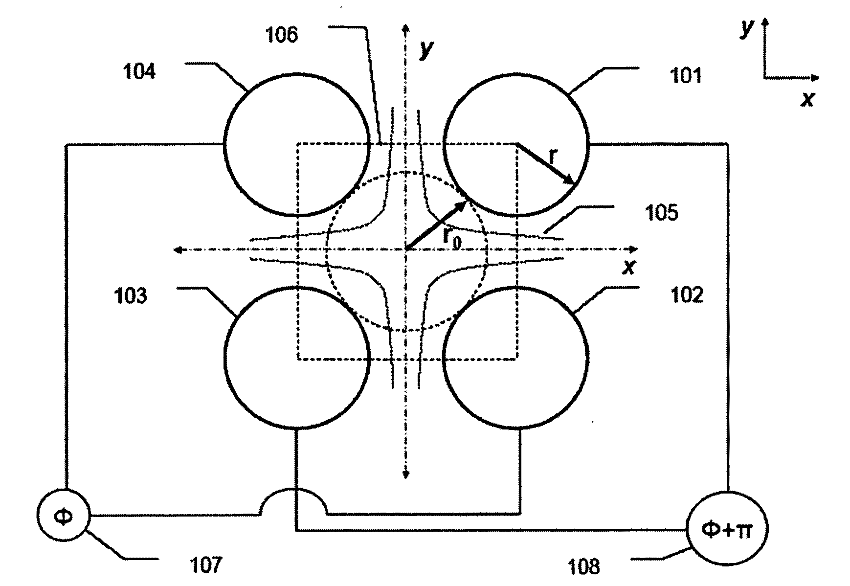
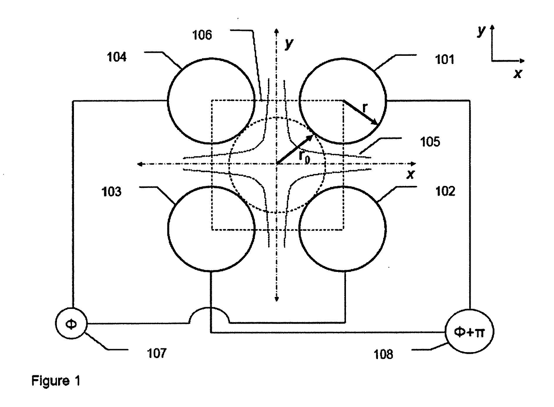
[0079]FIG. 1 is a cross section in the x-y plane of a quadrupole mass filter. Four circles 102, 102, 103 and 104 represent the four rods of the conventional quadrupole mass filter. The rods are connected to a RF voltage supply 107 and 108, and when the rods are driven by this supply an electrodynamic quadrupole field is generated between the rods. This field represented by the hyperbolic equipotential field lines 105, which is asymptotic to they and x axes at its extremities. The four circles 101, 102, 103 and 104 are tangentially intersected by an inscribed circle with a radius of r0. In a quadrupole, the centres of the four circles are equi...


PUM


Abstract

This invention describes an electrode structure formed from a plurality of individual electrodes, the plurality of electrodes being arranged relative to one another to define a three dimensional geometric structure with individual ones of the plurality of electrodes located at each of the vertices of the geometric structure and wherein each electrode of the cell presents a curved surface to each other electrode of the cell. Such a structure may be configured as a RF ion guide, mass filter or ion trap.

Description

CROSS-REFERENCE TO RELATED APPLICATIONS[0001]This application claims priority to United Kingdom Application GB0722038.7, filed Nov. 9, 2007, which is hereby incorporated by reference.FEDERALLY SPONSORED RESEARCH OR DEVELOPMENT[0002]Not Applicable.TECHNICAL FIELD[0003]The invention relates to electrode structures for use with charged particle beams. In particular, the invention provides for electrode structures that in various configurations act as an ion trap, ion guide, ion lens, collision cell or mass analyser to trap, transfer, collide, collimate, focus, analyse or filter a beam of ions. The electrode structure may be used to trap, guide or filter ions of interest, generated from a molecular beam, for analysis by their mass to charge ratio in an analytical instrument such as a mass spectrometer detector.BACKGROUND OF THE INVENTION[0004]Mass spectrometry (MS) is a powerful analytical technique that is used for the qualitative and quantitative identification of organic molecules, p...

Claims


Application Information

Patent Timeline
Patent Type & Authority Applications(United States)
IPC IPC(8): H01J49/26
CPCH01J49/424H01J49/0018
Inventor FINLAY, ALAN
Owner MICROSAIC SYST
Why Eureka
Try Eureka